41
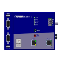
4 Electrical connection
4.3.3 Terminating resistors
The internal terminating resistors for the Com1 and Com2 interfaces are only relevant for
RS422/485.
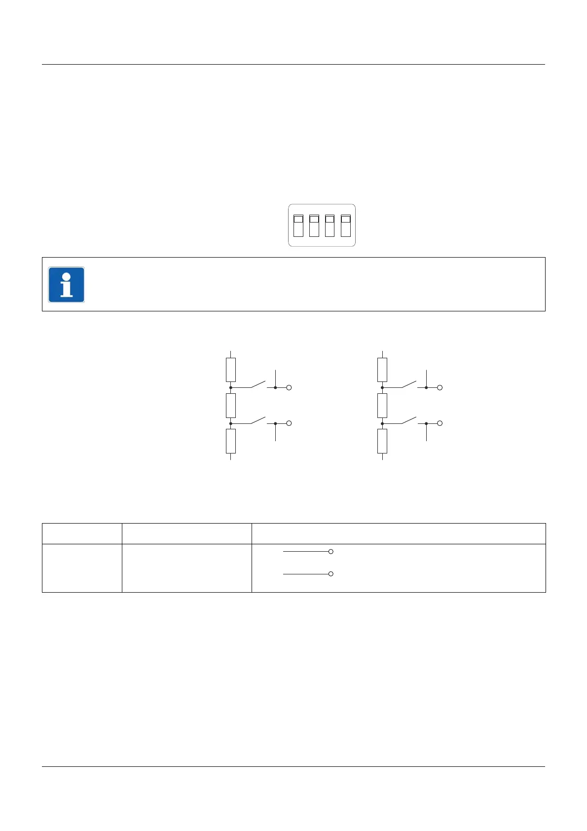
The terminating resistors are deactivated by default. To activate them, DIP switches 1 to 4 for
the relevant interface must be pushed upward using a suitable tool such as a ballpoint pen (ON
position).
The following figure shows the position of the DIP switches when the terminating resistors are
activated.
Internal terminating resistors
4.3.4 Voltage supply
NOTE!
To ensure fault-free operation, terminating resistors are required at the start and end of an
RS422/485 transmission path.
332 ?
120 ?
332 ?
GND
+5 V
4
9
332 ?
120 ?
332 ?
GND
+5 V
3
4
3
8
1
2
Connection Terminals Symbol and terminal designation
24 V DC +24 V and GND +24 V
GND