CAUTION: You must ensure that power connections maintain the proper
polarity. The power source cables might be labeled (+) and (–) to indicate
their polarity. There is no standard color coding for DC power cables. The
color coding used by the external DC power source at your site determines
the color coding for the leads on the power cables that attach to the
terminal studs on each power supply.
NOTE: For information about connecting to DC power sources, see “MX5,
MX10, MX40, and MX80 Routers DC Power Specifications” on page 59.
8. Replace the clear plastic cover over the terminals on the faceplate.
9. Verify that the power cables are connected correctly, that they are not touching or
blockingaccess to router components, and that they do not drape where people could
trip on them.
10. If you are installing two power supplies, repeat Steps 3 through 9 for the other power
supply.
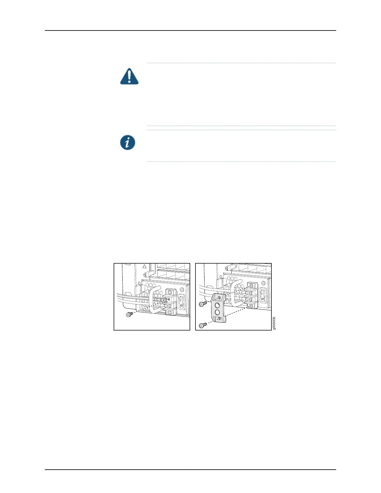
Figure 36: Connecting DC Power to the Router
Related
Documentation
Tools and Parts Required for MX5, MX10, MX40, and MX80 Router Grounding and
Power Connections on page 87
•
• Powering On a DC-Powered MX5, MX10, MX40, and MX80 Router on page 94
• MX5, MX10, MX40, and MX80 Router Grounding Specifications on page 43
93Copyright © 2017, Juniper Networks, Inc.
Chapter 15: Connecting the MX5, MX10, MX40, and MX80 Routers to Power