WARNING: Do not connect Power over Ethernet (PoE) enabled cables to
the console port. These cables are known to cause damage resulting in
console port failure.
Figure 39: Routing Engine Console and Auxiliary Cable Connector
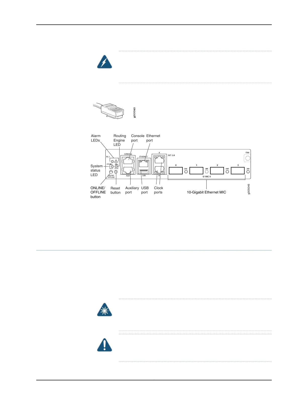
Figure 40: Auxiliary and Console Ports
g005046
ONLINE/
OFFLINE
Auxiliary
port
USB
port 10-Gigabit Ethernet MIC
Console
port
Ethernet
port
Clock
ports
Routing
Engine
LED
Alarm
LEDs
System
status
LED
Reset
button
ONLINE/
OFFLINE
button
Related
Documentation
Installing the MX5, MX10, MX40, and MX80 Cable Management Bracket on page 79•
• Connecting Interface Cables to MX5, MX10, MX40, and MX80 Routers on page 99
• Initially Configuring MX5, MX10, MX40, and MX80 Routers on page 101
Connecting Interface Cables to MX5, MX10, MX40, and MX80 Routers
To connect the physical interfaces to the network (see Figure 41 on page 100):
1. Have ready a length of the type of cable used by the component. For MIC cable
specifications, see the MX Series Interface Module Reference.
2. Remove the rubber safety plug from the cable connector port.
WARNING: Do not look directly into a fiber-optic transceiver or into the
ends of fiber-optic cables. Fiber-optic transceivers and fiber-optic cable
connected to a transceiver emit laser light that can damage your eyes.
CAUTION: Do not leave a fiber-optic transceiver uncovered except when
inserting or removing cable. The safety cap keeps the port clean and
prevents accidental exposure to laser light.
99Copyright © 2017, Juniper Networks, Inc.
Chapter 16: Connecting the MX5, MX10, MX40, and MX80 Routers to the Network