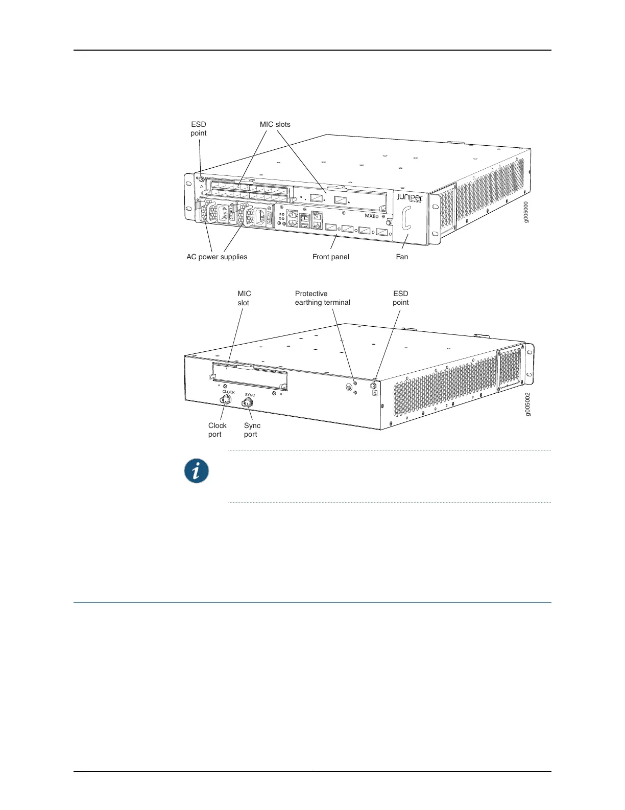
Figure 9: Front View of the MX80 Router (Modular Chassis)
g005000
Front panel Fan
MIC slots
AC power supplies
ESD
point
Figure 10: Rear View of the MX5, MX10, MX40, and MX80 Routers
g005002
CLOCK
SYNC
Clock
port
MIC
slot
Sync
port
ESD
point
Protective
earthing terminal
NOTE: The port labeled CLOCK provides 10 Mhz output. The port labeled
SYNC provides 1 PPS output.
Related
Documentation
MX5, MX10, MX40, and MX80 Router Overview on page 3•
• MX5, MX10, MX40, and MX80 Router Models on page 5
• MX5, MX10, MX40, and MX80 Routers Physical Specifications on page 41
MX5, MX10, MX40, and MX80 Baseboard Description
The baseboard is located in the center of the chassis and forms the rear of the MIC card
cage. The baseboard is not replaceable. The MICs and power supplies install into the
baseboard from the front of the chassis. Data packets are transferred across the
baseboard from the MIC to the Packet Forwarding Engine, and from the Packet Forwarding
Engine across the baseboard to the destination MIC.
11Copyright © 2017, Juniper Networks, Inc.
Chapter 2: Chassis Components and Descriptions