The following sample calculationfor an 8-km-long single-mode link with a power budget
(P
B
) of 13 dB uses the estimated values from Table 34 on page 68 to calculate link loss
(LL) as the sum of fiber attenuation (8 km @ 0.5 dB/km, or 4 dB) and loss for seven
connectors (0.5 dB per connector, or 3.5 dB). The power margin (P
M
) is calculated as
follows:
P
M
= P
B
– LL
P
M
= 13 dB – 8 km (0.5 dB/km) – 7(0.5 dB)
P
M
= 13 dB – 4 dB – 3.5 dB
P
M
= 5.5 dB
In both examples, the calculated power margin is greater than zero, indicating that the
link has sufficient power for transmission and does not exceed the maximum receiver
input power.
Related
Documentation
Understanding Fiber-Optic Cable Signal Loss, Attenuation, and Dispersion on page 66•
Routing Engine Interface Cable Specifications for MX5, MX10, MX40, and MX80 Routers
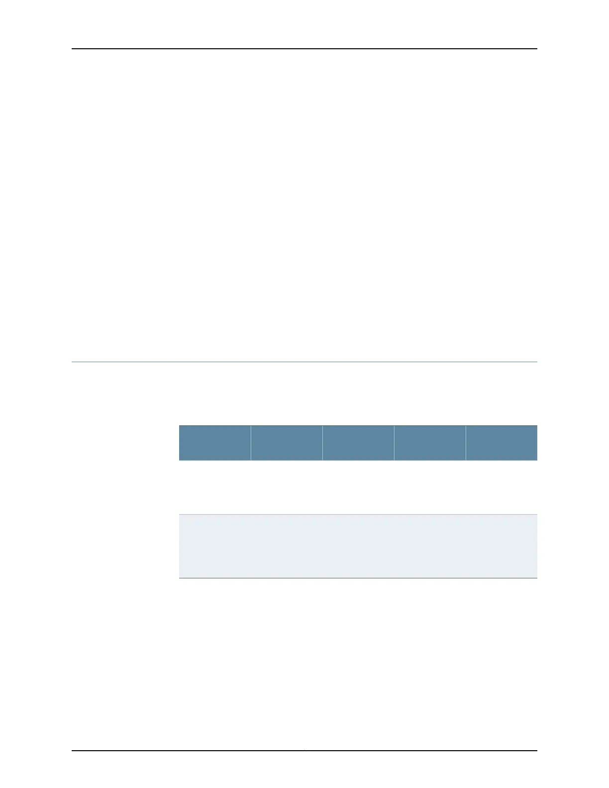
Table 35 on page 69 lists the specifications for the cables that connect to management
ports.
Table 35: Cable Specifications for Routing Engine Management
Router
Receptacle
Maximum
Length
Cable/Wire
Supplied
Cable
SpecificationPort
RJ-45 female6 ft (1.83 m)One 6-ft
(1.83-m) length
with RJ-45/DB-9
connectors
RS-232
(EIA-232) serial
cable
Routing Engine
console or
auxiliary
interface
RJ-45
autosensing
328 ft (100 m)One 15-ft
(4.57-m) length
with
RJ-45/RJ-45
connectors
Category 5 cable
or equivalent
suitable for
100Base-T
operation
Routing Engine
Ethernet
interface
Related
Documentation
• MX5, MX10, MX40, and MX80 Routing Engine Description on page 21
• Maintaining the MX5, MX10, MX40, and MX80 Routing Engine on page 162
• RJ-45 Connector Pinouts for the ETHERNET Port on MX5, MX10, MX40, and MX80
Routers on page 72
• RJ-45 Connector Pinouts for the AUX and CONSOLE Ports on MX5, MX10, MX40, and
MX80 Routers on page 71
69Copyright © 2017, Juniper Networks, Inc.
Chapter 10: Transceiver and Cable Specifications