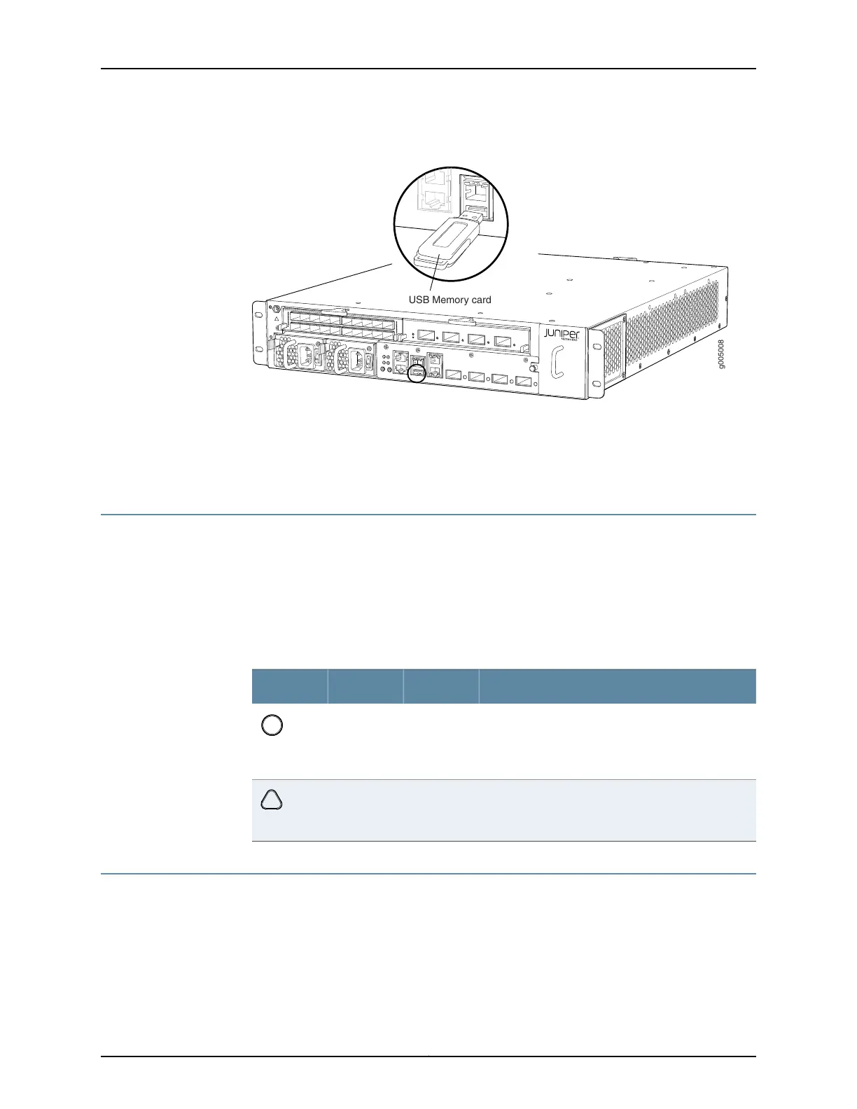
Figure 14: USB Memory Device in an MX5, MX10, MX40, and MX80 Router
Related
Documentation
Alarm LEDs on the MX5, MX10, MX40, and MX80 Front Panel on page 15•
• Component LEDs on the MX5, MX10, MX40, and MX80 Front Panel on page 15
Alarm LEDs on the MX5, MX10, MX40, and MX80 Front Panel
Two alarm LEDs are located at the left of the front panel. The circular red LED lights to
indicate a critical condition that can result in a system shutdown. The triangular yellow
LED lights to indicate a less severe condition that requires monitoring or maintenance.
Both LEDs can be lit simultaneously.
Table 8 on page 15 describes the alarm LEDs in more detail.
Table 8: Alarm LEDs on the MX5, MX10, MX40, and MX80 Front Panel
DescriptionStateColorShape
Critical alarm LED—Indicates a critical condition that
can cause the router to stop functioning. Possible
causes include component removal, failure, or
overheating.
On steadilyRed
Warning alarm LED—Indicates a serious but nonfatal
error condition, such as a maintenance alert or a
significant increase in component temperature.
On steadilyYellow
Component LEDs on the MX5, MX10, MX40, and MX80 Front Panel
•
Link LEDs on the Front Panel on page 16
•
Routing Engine LED on the Front Panel on page 16
•
System LED on the Front Panel on page 16
15Copyright © 2017, Juniper Networks, Inc.
Chapter 2: Chassis Components and Descriptions