8. Replace the clear plastic cover over the terminals on the faceplate.
9. Verify that the power cabling is correct, that the cables are not touching or blocking
access to router components, and that they do not drape where people could trip on
them.
10. On each of the DC power supplies, switch the DC circuit breaker to the center position
before moving it to the on ( | ) position.
NOTE: The circuit breaker may bounce back to the off (O) position if you
move the breaker too quickly.
NOTE: If more than one power supply is being installed, turn on all power
supplies at the same time.
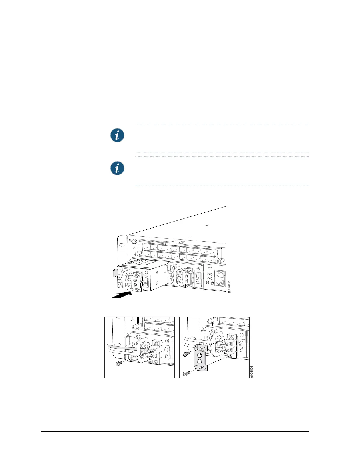
Figure 62: Installing a DC Power Supply
Figure 63: Connecting the DC Power Cables
Related
Documentation
MX5, MX10, MX40, and MX80 Power System Description on page 35•
• Removing an MX5, MX10, MX40, and MX80 DC Power Supply on page 143
Copyright © 2017, Juniper Networks, Inc.142
MX5, MX10, MX40, and MX80 3D Universal Edge Router Hardware Guide