MX5, MX10, MX40, and MX80 Router Grounding Specifications
•
Grounding Points Specifications on page 43
•
Grounding Cable Lug Specifications on page 43
•
Grounding Cable Specifications on page 44
Grounding Points Specifications
To meet safety and electromagnetic interference (EMI) requirements and to ensure
proper operation, the router must be adequately grounded before power is connected.
To ground AC-powered and DC-powered routers, you must connect a grounding cable
to earth ground and then attach it to the chassis grounding points using the two screws
provided (see Figure 24 on page 43).
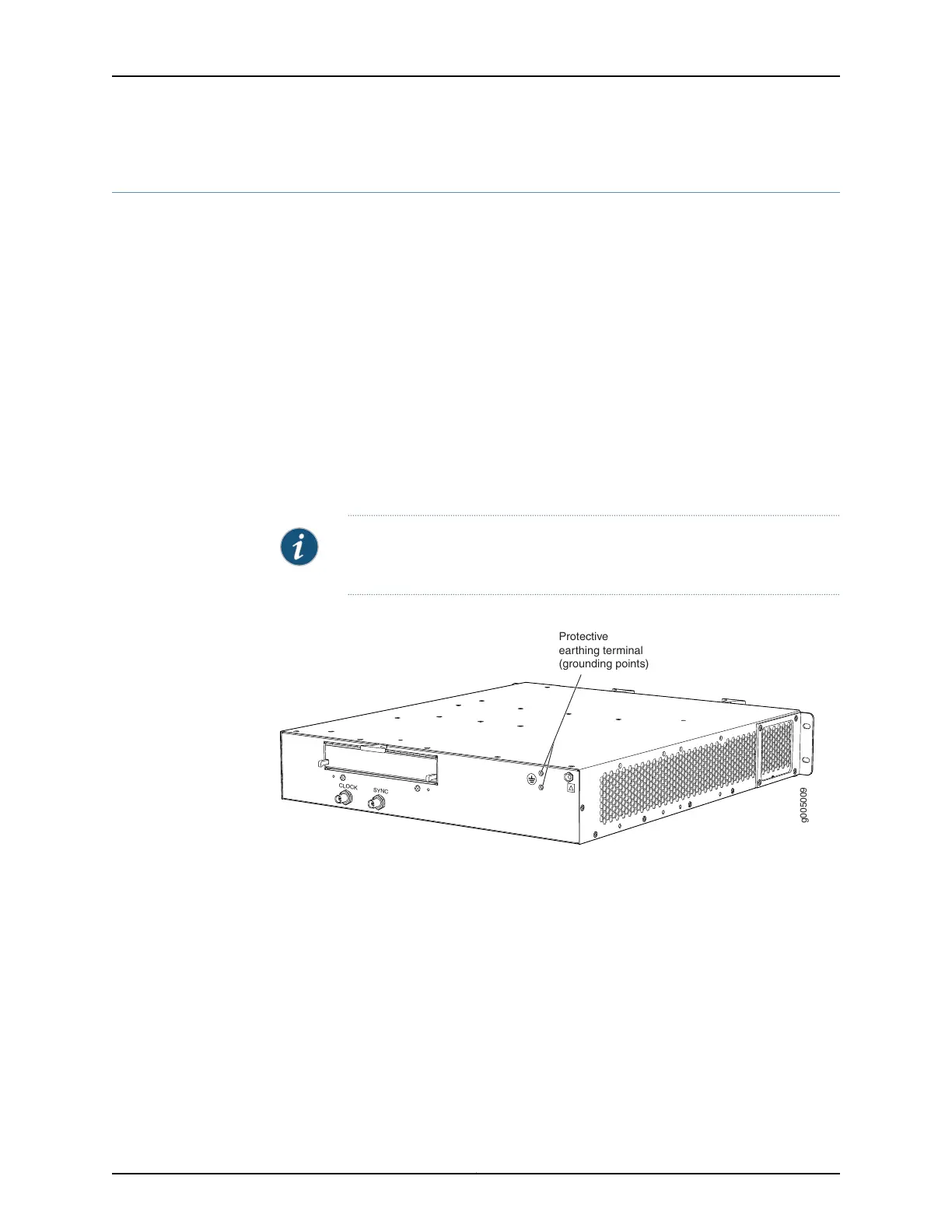
Two threaded holes are provided on the upper rear of the chassis for connecting the
router to earth ground. The grounding points fit SAE 10-32 screws (American). The
grounding points are spaced at 0.625-in. (15.86-mm) centers.
NOTE: Additional grounding is provided to an AC-powered router when you
plug its power supplies into grounded AC power receptacles.
Figure 24: Grounding Points on MX5, MX10, MX40, and MX80 Routers
g005009
CLOCK
SYNC
Protective
earthing terminal
(grounding points)
Grounding Cable Lug Specifications
The accessory box shipped with the router includes one cable lug that attaches to the
grounding cable (see Figure 25 on page 44) and two SAE 10–32 screws used to secure
the grounding cable to the grounding points.
43Copyright © 2017, Juniper Networks, Inc.
Chapter 7: Preparation Overview