N9030B PXA Signal Analyzer Service Guide 263
LO Synthesizer/Reference Troubleshooting
A14 LO Synthesizer and A20 YTO Troubleshooting
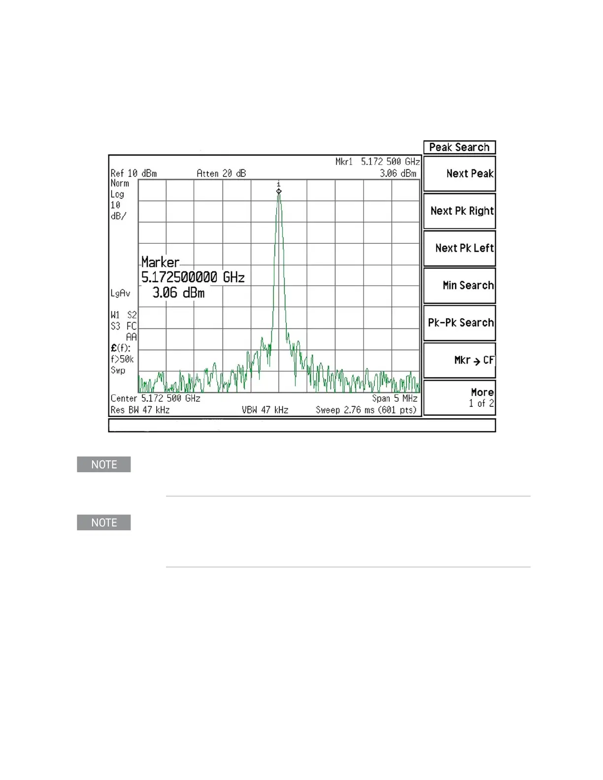
8. The analyzer marker should read 5172.5 MHz at 0 dBm ± 4 dB as shown in
Figure 8-9.
Figure 8-9 5.1725 GHz 1st LO Measurement
9. Continue changing the center frequency of the PXA as per Table 8-2 and
measure the LO output expected frequency and power using the
functioning spectrum analyzer. Frequencies above 3.6 GHz apply only to
analyzers with Option 508, 513, or 526.
10.If measurements made with the connections above do not indicate a
failure, but failures (i.e. 1st LO unlocks) do occur when the cables are
connected normally (i.e. with the A20 YTO output feeding the A13A1 RF
Front End Assembly and A13A1 feeding the A14 LO Synthesizer), the most
probable cause is the LO distribution section on A13A1.
Due to the nominal 10 dB coupling factor of the directional coupler, the
actual power at the YTO output will be approximately 10 dB higher than
the power level measured by the functioning spectrum analyzer.
If the 5172.5 MHz signal is not measuring the correct power level but the
frequency is correct, the A20 YTO is the most probable cause. If the power
level is correct, but the frequency is not correct, the A14 LO Synthesizer is
the most probable cause.