466 N9030B PXA Signal Analyzer Service Guide
Assembly Replacement Procedures
RF Area (Options 503, 508, 513, 526)
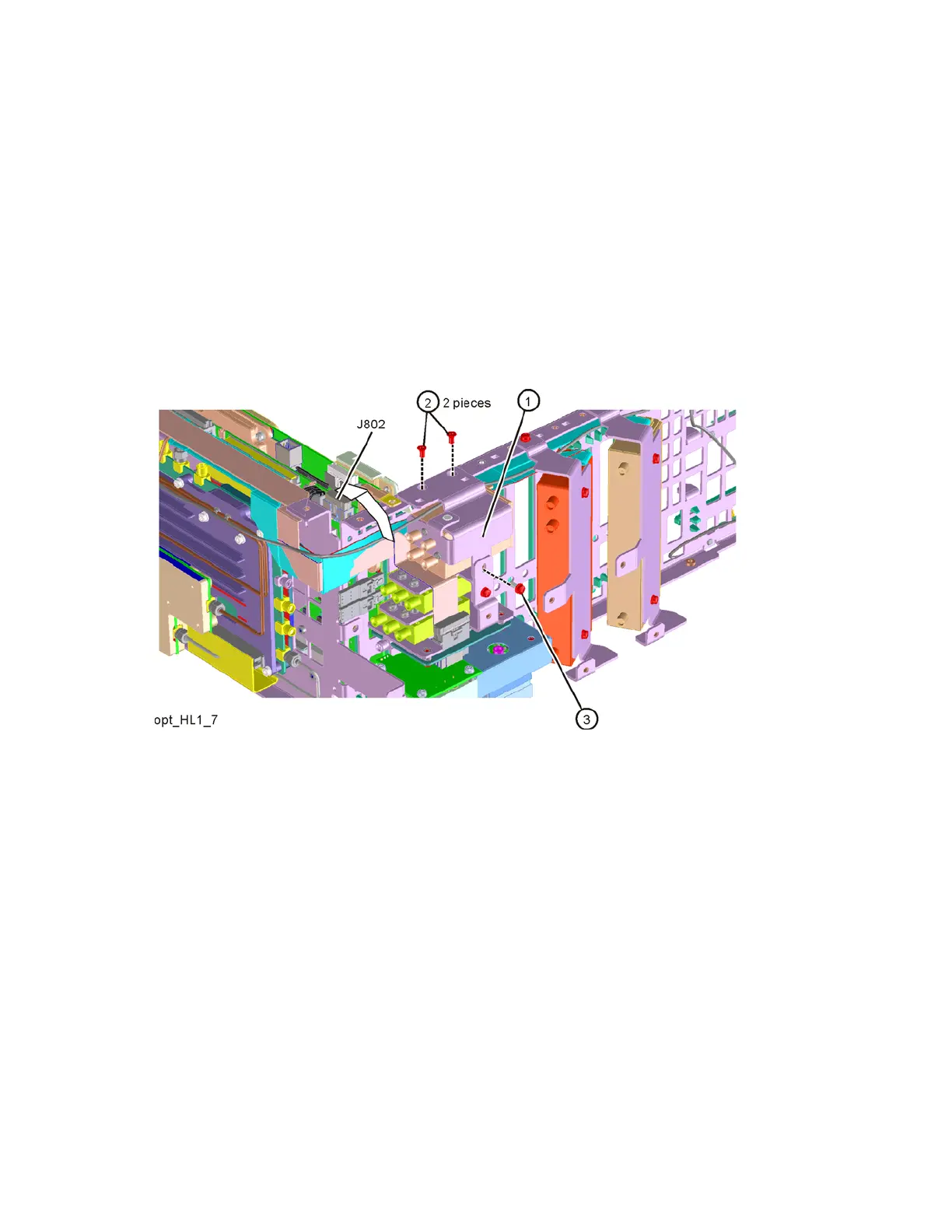
9. Refer to Figure 16-34. Install the switch assembly (1). Route the switch
control cable between the switch and the chassis. The cable routes over
the LO Synthesizer board ear then plugs into J802. If this is not routed
correctly the cable can be damaged when the top brace is installed. Refer
to Figure 16-35 and Figure 16-36 for cable routing pictures. Connect the
ribbon cable to the Front End Controller J802 as shown. Secure switch
bracket to chassis frame with the two top screws (2) (0515-2032). Secure
switch bracket to the other switch bracket with the single side screw (3)
(0515-0372). Torque screws to 9 inch-lbs.
Figure 16-34 Switch Assembly Installation