60 N9030B PXA Signal Analyzer Service Guide
Boot Up and Initialization Troubleshooting
Potential Problems During Boot Process
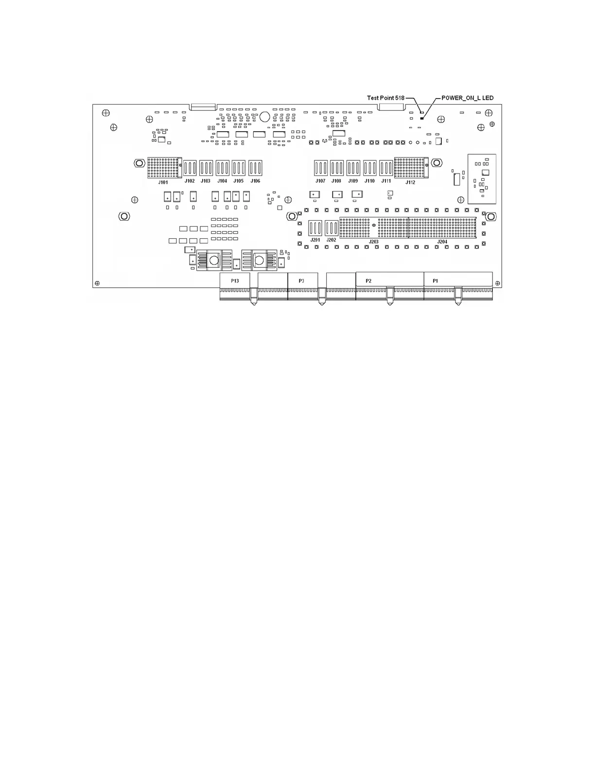
Figure 2-4 A7 Midplane Board - Test Point 518/POWER_ON_L LED
5. Turn the instrument power on from the front panel On/Off button and view
the status of the POWER_ON_L LED, as shown in Figure 2-4.
Does the POWER_ON_L LED come on? (Test Point 518 should also go to 0
VDC)
If yes:
Proceed to step 6.
If not:
Verify the connection between the front panel On/Off switch and the
A4 Processor assembly by checking the status of the POWER_SW_L
control line when the front panel On/Off button is both pressed and
released. This can be monitored by measuring the voltage at Test
Point 520, as shown in Figure 2-5.
With the On/Off button released this should measure a TTL high
level, and with the button pressed it should measure a TTL low level.
The A4 Processor board assembly provides the voltage and the
switch on the front panel pulls it low when it is pressed.