EasyManuals Logo

Malvern Mastersizer 3000 User Manual

Malvern Mastersizer 3000
182 pages
To Next Page IconTo Next Page
To Previous Page IconTo Previous Page
Page #21 background imageLoading...
Page #21 background image
Introducing the Mastersizer 3000 Chapter 2
Mastersizer 3000 Page 2-9
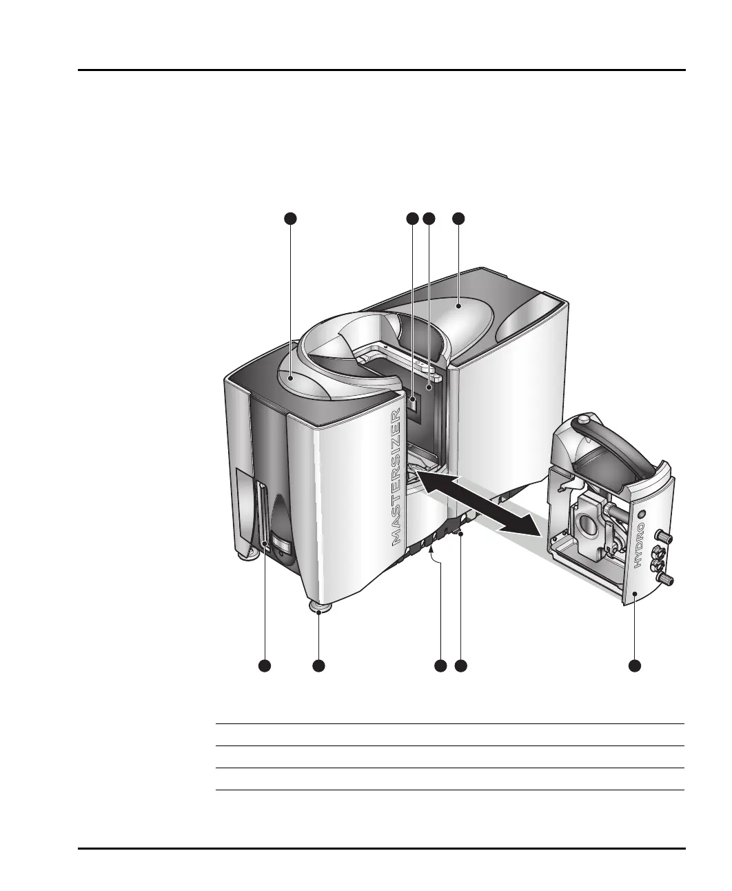
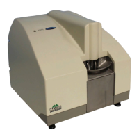
Optical unit components
This diagram shows the optical unit, the main component of the Mastersizer
system. The unit directs red and blue light through the sample and then collects the
light scattered by the particles within the sample using a set of light-sensitive detec
-
tors. This data enables the system to calculate particle size:
ill 8622
Optical unit
Protection window
Cell
Adjustable feet
Instrument status LED
Drain
Cell bay
Tube/cable routing guide
End panel
1
3
4
6
2
5
7
8
9

Table of Contents

Other manuals for Malvern Mastersizer 3000

Questions and Answers:

Question and Answer IconNeed help?

Do you have a question about the Malvern Mastersizer 3000 and is the answer not in the manual?

Malvern Mastersizer 3000 Specifications

General IconGeneral
Measurement principleLaser diffraction
Blue laser wavelength470 nm
Sample dispersion optionsWet and dry dispersion
Data acquisition rate10 kHz
Particle size range0.01 to 3500 microns
Laser typeHe-Ne and solid state
AccuracyBetter than 1%
RepeatabilityBetter than 0.5%
TechnologyMie and Fraunhofer theories
Sample dispersion unitsHydro MV, Hydro LV, Aero S
Optical modelMie theory
Power requirements100-240 V, 50/60 Hz
Detector arrangementLog-spaced array

Related product manuals