Manitowoc Published 10-01-2012, Control # 045-08 10-53
777 SERVICE MANUAL TROUBLESHOOTING
10
Test 23 – Transducer Test
Testing the voltage and resistance at a transducer requires a
standard test plug adapter (which can be ordered from
Manitowoc Cranes, Inc.) and a digital multimeter. Connect
the test plug adapter between the desired transducer and its
electrical connector. Turn the cab power switch on with
engine off.
To test incoming power, make the appropriate connections
from the adapter cable to the digital multimeter for testing
incoming power (white + and black -) and verify
approximately 12 volts DC. If this reading is not obtained,
check the F10 (10 amp) fuse at the fuse box (see Test 6).
When checking for the correct voltage output from the
transducer to the programmable controller, test with engine
off/power on. Make the appropriate connections at the digital
multimeter (green + and black -) and verify 1.00 to 1.04 volts
DC. Note: the PC nulling routine permits the equipment to
operate outside of the 1.00 to 1.04 voltage range. However, if
readings less than or equal to 0.50 volts, or greater than or
equal to 2.0 volts are obtained, the transducer must be
changed.
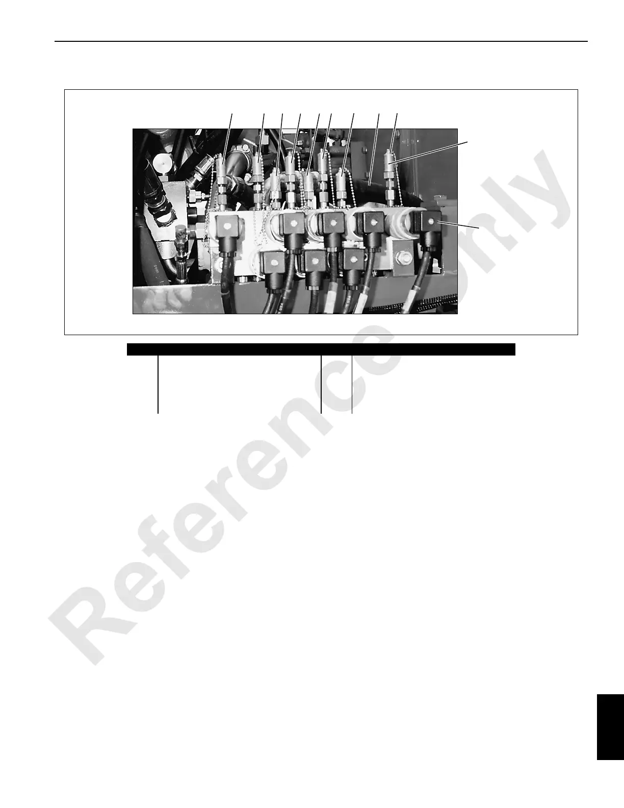
Item Description Item Description
1 Left Track Forward/Reverse 6 Boom Hoist Pump (Boom Up)
2 Right Track Forward/Reverse 7 Front Load Drum Hoist
3 Swing Left 8 Rear Load Drum Hoist
4 Swing Right 9 Auxiliary Load Drum Hoist (optional)
5 Boom Hoist Cylinder (Boom Up)
FIGURE 10-28
P697
Electrical
Diagnostic
Gauge Couplers
DIN Connector
1 23 54 6 87 9

 Loading...


