Driving modes and rigging for on-road driving
6.3 Removing/installing main boom
6 - 18 3 112 993 en Operating manual GMK 6400
12.07.2013
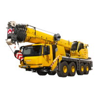
6.3.3 Slinging the main boom
Slings are fitted to the main boom when rigging and it is lifted with an aux-
iliary crane. Note the equipment necessary for this;
à p. 6 - 11.
Marking The lifting gear is labelled.
Only connect the parts of the lifting gear that
have the same marking.
Only fasten the lifting gear to the slinging
points intended for this purpose. The mark-
ings are of following significance:
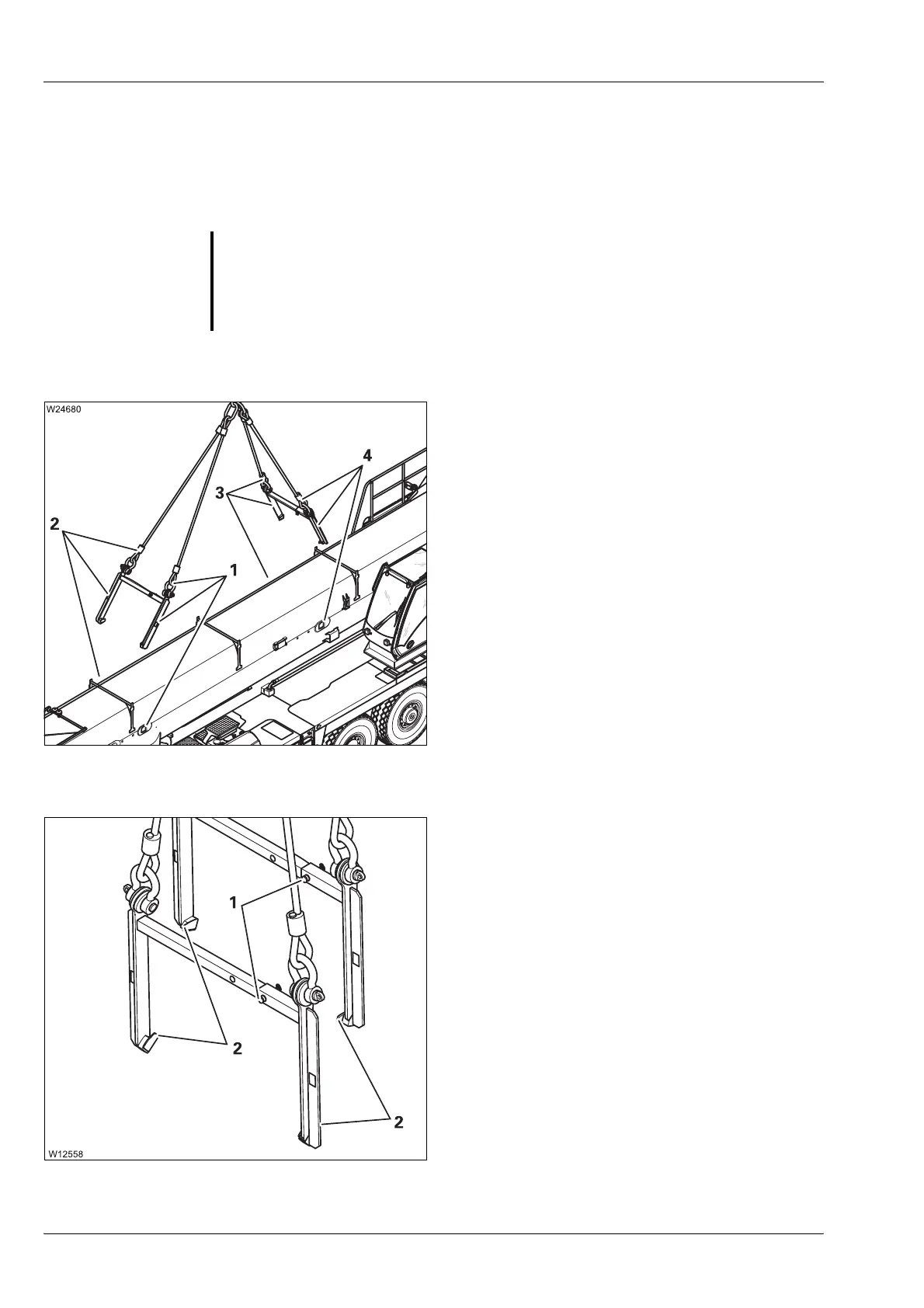
Installing the
lifting gear
• If the installation is correct, the load-bearing
equipment (2) of both brackets point to each
other
• Lock both brackets in the wide position
Secure the pins (1) using the retaining pins
• Install the front bracket first. It hangs on
longer ropes, which makes installing the
back bracket easier
G
Risk of accident from incorrect procedure
Only use the lifting gear included in the delivery and proceed as described
in the following section.
1 VL – Front left
2 VR – Front right
3 HR – Rear right
4 HL – Rear left
 Loading...