Operating elements for crane operation
9.2 Short description of the operating elements
Operating manual GMK 6400 3 112 993 en 9 - 83
12.07.2013
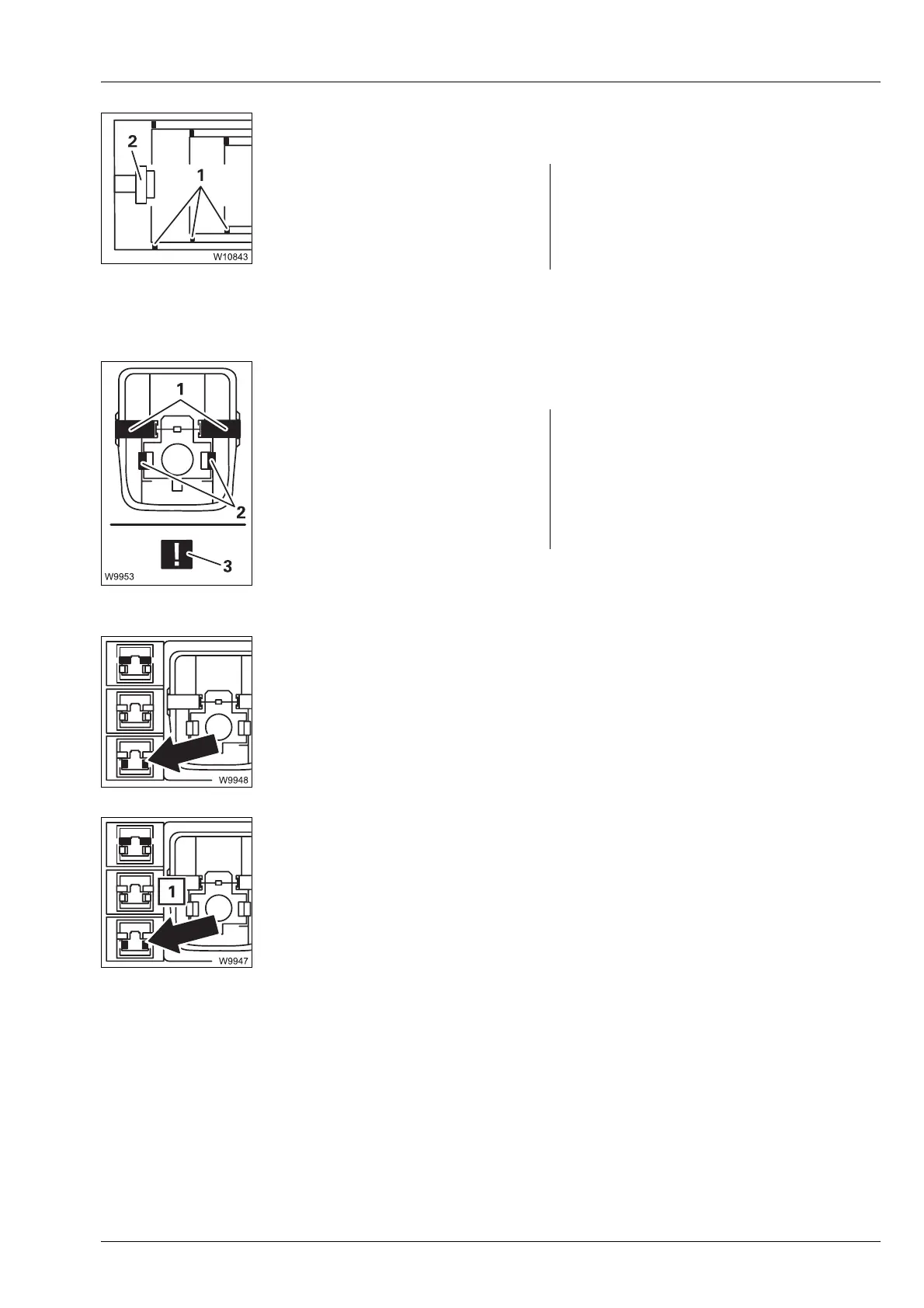
Telescope diagram display
Current relation between the telescopic sections – section of top view.
Locking status display
The locking pins change the position and colour.
Unlock telescoping cylinder selection
s
Locking pin Display 1 and 2
1 On the telescopic section – Green: Locked
2 On the telescoping cylinder – None: Unlocked or interme-
diate position
à p. 11 - 80
Locking pin Display 1 and 2
1 On the telescopic section – Green: Locked
2 On the telescoping cylinder –Red: Unlocked
– Yellow: Intermediate position
– Violet: Error – symbol (3)
à p. 11 - 81
– Display Yellow: Telescoping cylinder unlocked
Grey: Telescoping cylinder locked
Flashing:
(yellow/grey)
Unlock selected
– To select: Press button 1 x
– Telescopic section locked:
Unlock selected – executed after moving the control lever
– Telescopic section unlocked:
Unlock not selected – symbol (1) flashes (yellow/grey) as
a prompt to
Lock telescopic section
à p. 11 - 81

 Loading...