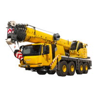
Operating elements for driving
3.1 Overview of the operating elements
Operating manual GMK 6400 3 112 993 en 3 - 3
12.07.2013
1 Front flap à p. 3 - 64
2 Driver's cab
à p. 3 - 4
3 Valves on hydraulic tank
à p. 4 - 11
4 Hydraulic oil cooler, second cooler
1)
5 Hydraulic emergency operation à p. 14 - 59
6 Switching on boom floating position
Switching on boom pre-tensioning
à p. 6 - 8
à p. 6 - 9
7 Removal of the main boom
1)
8 Spare wheel
1)
à p. 1 - 10
9 Chocks
à p. 5 - 53
10 Outriggers, operation
Outrigger lighting
Installing/removing outrigger beams
Installing/removing the supporting box
1)
à p. 12 - 29
à p. 3 - 57
à p. 6 - 35
à p. 6 - 53
11 Ladders
à p. 4 - 5
12 Outrigger control units
1)
Emergency stop switch
Sockets for hand-held control
à p. 3 - 29
à p. 4 - 26
à p. 3 - 28
13 Fuel tank
Dual system fuel tank
1)
à p. 4 - 8
à p. 4 - 9
14 Connection for battery charger
1)
à p. 7 - 11
15 Adjusting the mirrors
à p. 5 - 6
16 Battery master switch
à p. 4 - 12
17 Filler connection for the compressed air system
Tyre inflator connection
à p. 7 - 6
à p. 7 - 17
18 Warning plates for vehicle width
à p. 5 - 8
19 Air intake inhibitor
1)
à p. 4 - 27
20 Engine
à p. 4 - 1
21 External starting socket
1)
à p. 7 - 11
22 Access ladders
à p. 4 - 4
23 DEF tank
1)
24 Battery master switch à p. 4 - 12
25 Switching on the slewing gear freewheel
1)
à p. 6 - 7
26 Switching the superstructure driving lights on/off
1)
à p. 6 - 10
27 Control unit
– Locking pin
– Auxiliary supports
à p. 3 - 30
28 Reverse camera
1)
Additional equipment

 Loading...


