Malfunctions during crane operation
14.5 Emergency operations and programmes
Operating manual GMK 6400 3 112 993 en 14 - 49
12.07.2013
Error on proximity
switch
Faulty proximity switches are shown in violet.
The displays (A), (B) and (C) only show the current positions when all the
corresponding proximity switches are free of error.
Several proximity switches are related to the
displays (A), (B) and (C).
When a proximity switch is faulty (violet),
then:
– The corresponding locking pins on the dis-
plays (A) and (B) are always yellow
– The corresponding arrows are not shown on
the display (C)
When an error occurs, you can determine the current position more pre-
cisely based on the other, fault-free proximity switches. The proximity
switches show the following positions:
– Display (C) – Telescoping cylinder at the locking point
– Display (B) – Telescopic section locked
– Display (A) – Telescoping cylinder locked
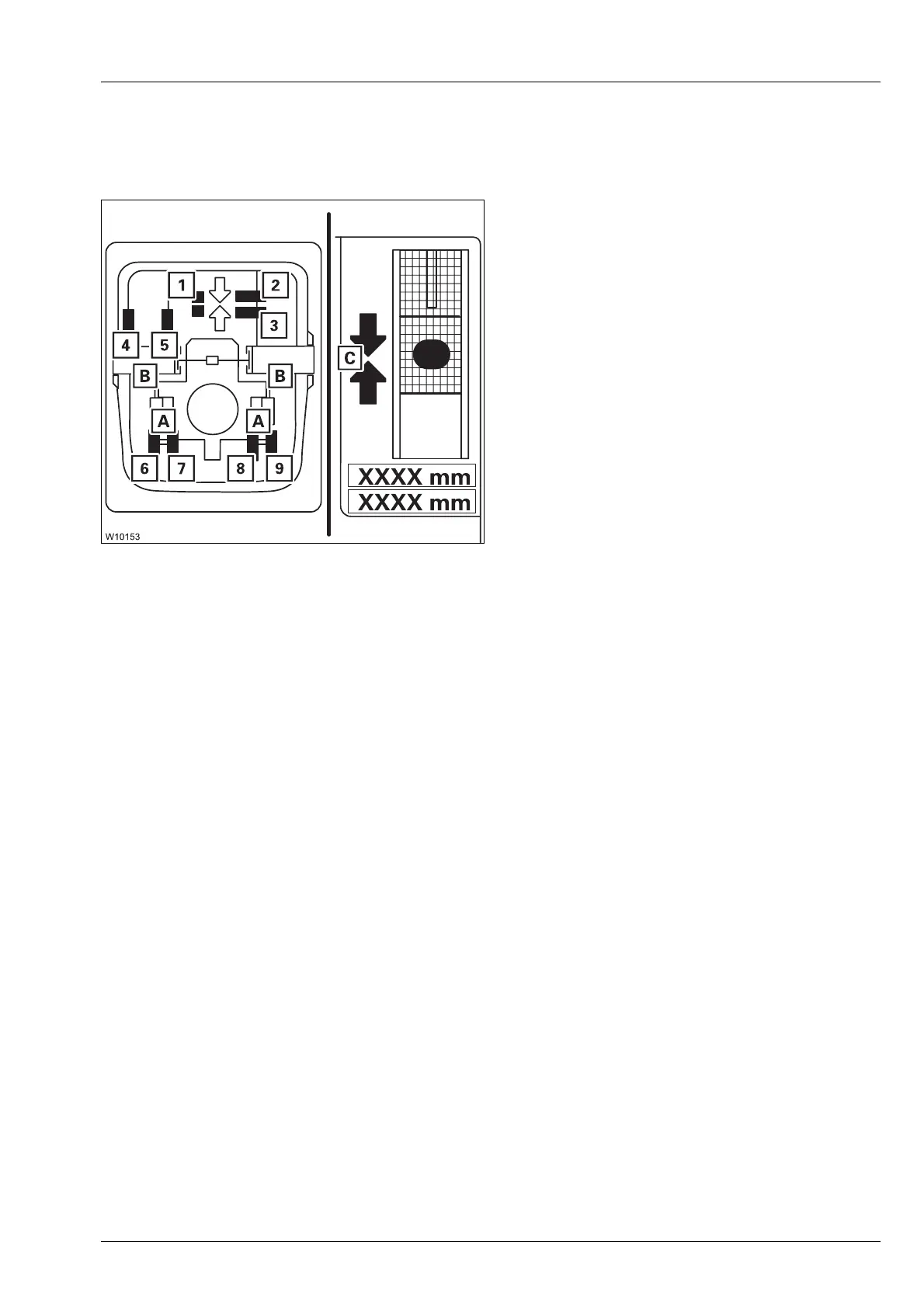
For fault-free proximity switches, the following applies:
s
For A: Proximity switches (6) to (9)
For B: Proximity switches (4) and (5)
For C: Proximity switches (1) to (3)
1 At the locking point
2 Behind the locking point
3 In front of the locking point
4 Locked
5 Unlocked
6 Locked left
7 Unlocked left
8 Unlocked right
9 Locked right
–Green:Position reached
–Red: Position not reached

 Loading...