31 Installation and start-up Page 132 of 142
MCS301 meter - product Manual 1.25 MetCom Solutions GmbH
31 Installation and start-up
31.1 Installation and general function control
The meter is mechanically secured in place by first suspending it in the upper eye, and screwing
it into position through the two bottom mounting points to the left and right of the terminal block,
which are 150 mm apart in conformity with the dimensions laid down in DIN 43857. The
suspension eye enables the meter to be installed in either an open or concealed configuration
as desired. Using these 3 mounting points, the meter is installed on a meter panel.
As soon as the meter has been connected to the power supply, a corresponding indicator in the
display will show that the phase voltages L1 to L3 are present.
If the meter has started up, this will be indicated directly by an arrow in the display, and by the
energy pulse LED, which will flash in accordance with the preset pulse constant.
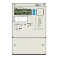
1
Figure 23: Front view of the MCS301
1 – Main seals
2 – 2 alternate push buttons (up/down)
3 – Optical interface
4 – Name plate
5 – Part of splitted terminal cover (for communication module protection)
6 – Part of splitted terminal cover (for meter terminal protection)
7 – Utility seals
8 – CT/VT ratio name plate, ext. battery, demand reset push button access
9 – LED for optical test output – active energy
10 – Meter LCD
11 – LED for optical test output – active energy