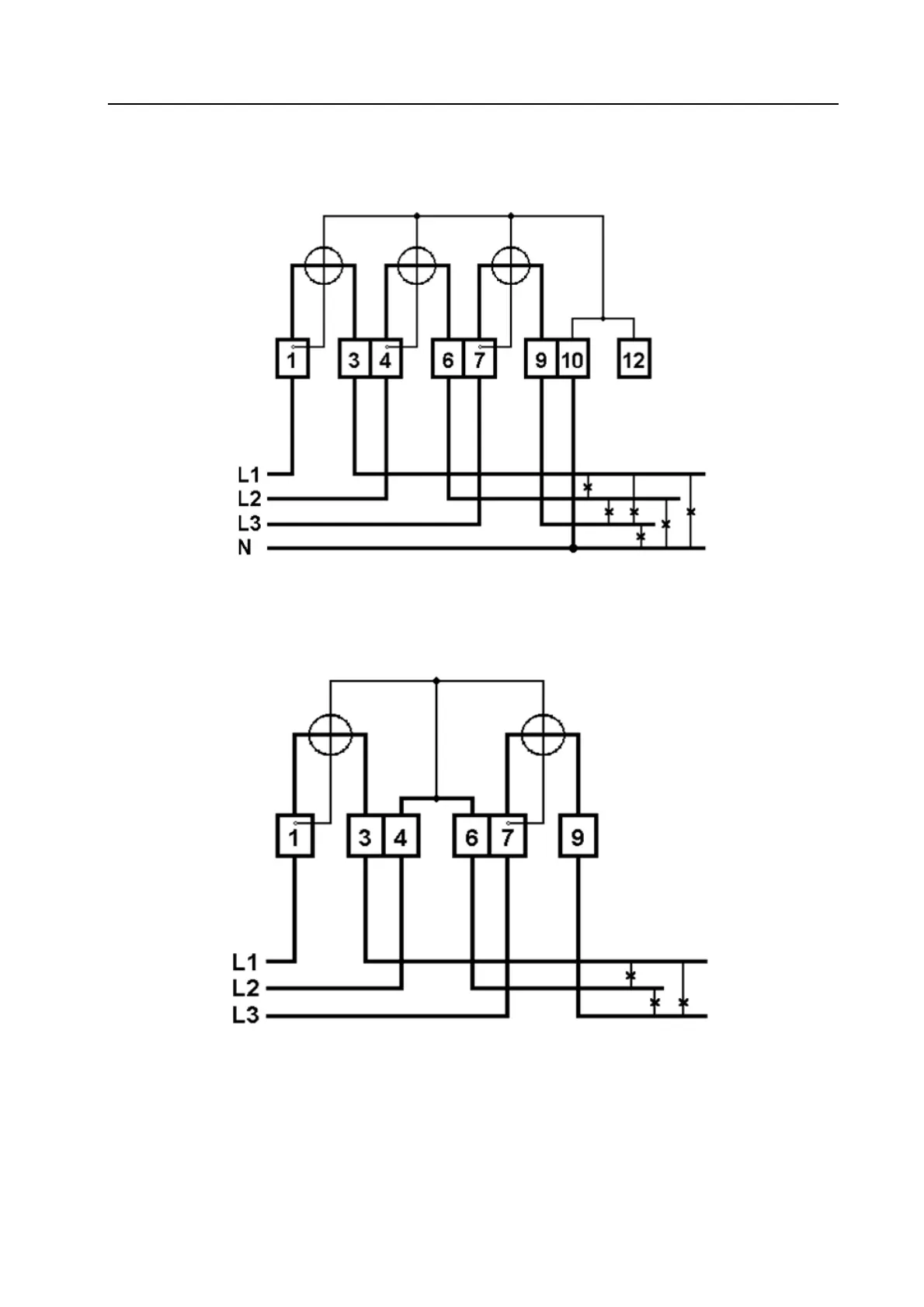
Home
Metcom Solutions
Measuring Instruments
MCS301
Metcom Solutions MCS301 User Manual
5
of 1
of 1 rating
142 pages
Give review
Manual
Specs
To Next Page
To Next Page
To Previous Page
To Previous Page
Loading...
34 Connection
diagram
Page 139 of 14
2
MCS301 m
eter - product
Manual 1.25
MetCom Solut
ions Gm
bH
34.2
Mains co
nnectio
n diagram
The main connection
diagram is shown
in the followi
ng figures
Figure 34: 4-wire meter (3
Solutions), direct connection
Figure 35: 3-wire meter (2
Solutions), direct connection
138
140
Table of Contents
Table of Contents
3
Overview
8
Referenced Documents
9
Definitions and Abbreviations
10
Meter Standards
11
Meter Approvals
11
Safety and Maintenance Information
12
Responsibilities
12
Safety Instructions
12
Maintenance
13
Disposal
13
Basic Functionality
14
General Concept
15
Application Relevant FW Part
16
Metrological Relevant FW Part
16
Meter Construction
17
Front View
17
Outside Meter Dimensions
18
Meter Case Parts
19
Terminal Block
19
CT Connected Terminal Block
19
Direct Connected (DC) Terminal Block
20
Main Cover
21
Terminal Cover
21
Communication Module Cover
22
Sealing
22
Name Plate
23
Display Control
24
Display
24
Back Lightened Display
25
Display Formats
26
Display of Unit Parameters
26
Display of Decimals
26
Display of MID Relevant Data on the LCD
26
Display Modes
27
Scroll Mode
28
Different Display Mode
29
Display Test Mode
29
Alternate Mode (A-Button Menu)
29
Standard Mode (Menu Option "Std-Data")
29
Metrological Relevant Standard Mode (Menu Option "Protect Std-Data")
29
Service Mode (Menu Option "Ser-Data")
29
Load Profile 1 - "Standard Profile" - (Menu Option
30
Load Profile 2 - "Daily Profile" - (Menu Option
30
Reset Mode (R-Button Menu)
31
High Resolution Mode for Test Purposes (Menu Option „Test")
31
Activation of Push Mode (Menu Option „Cell Connect")
31
Activation of M-Bus Installation (Menu Option „Slave_Install")
31
Optical Display Sensor
31
Measurement Functionality
32
Measuring Principle
32
Calculation of Voltage and Current
32
Calculation of Active/Reactive and Apparent Demand
32
Calculation of Harmonics and THD
32
Measuring Methods
33
Standard Measuring Method (Vectorial Method)
33
Absolute Measuring Method (Optional)
33
Arithmetic Measuring Method (Optional)
33
Measurement Data
34
Energy Measurement
34
Energy Measurement (3Ph Values)
34
Energy Measurement (3Ph Values) - Since Last Demand Reset
35
Energy Measurement (1Ph Measurement)
35
Maximum Demand Measurement
36
Instantaneous Measurement
37
Instantaneous Measurement - Demand Data
37
Instantaneous Measurement Data - PQ Data Without Harmonics
37
Instantaneous Measurement Data - PQ Data with Harmonics + THD
38
Average- / Min- / Max- Interval Data
39
Last Average Values
39
Last Minimum Values
40
Last Maximum Values
40
Primary / Secondary Measurement
41
Secondary Measurement
41
Primary Measurement
41
Meter Registration
42
Meter Identification
42
System Title
42
Logical Device Name
43
Utility Device ID
44
Meter Registration Using Data Notification Service
44
Tariff Management
45
Activity Calendar
46
Special Day Table
46
Register Activation
46
Real Time Clock
47
General Characteristics of the Real Time Clock
47
Battery Backup
47
Internal Battery
47
External Battery
47
Time & Date Handling
48
DST Time Change
48
End of Billing / Demand Reset
49
End of Billing Sources
49
General Behavior
49
End of Billing Profile Register (Historical Data)
50
Data Model and Protocol
51
Data Model
51
Protocol
51
DLMS Protocol Only
51
EN62056-21 and DLMS Protocol
52
Load Profile
53
General Profile Structure
53
Sort Method
53
Buffer Reading
54
Profile Status
54
Effect of Events on Load Profiles
55
Capture Period
60
Load Profile 1 - Standard Profile
61
Load Profile 2 - Daily Profile
62
Load Profile 3 - Average Profile
63
Load Profile 4 - Maximum Profile
64
Load Profile 5 - Minimum Profile
65
Load Profile 6 - Harmonics and THD Values
66
Snapshot Profiles of Instantaneous PQ And/Or Energy Values
68
Instantaneous Energy Profile
68
Instantaneous Power Quality Profile
68
Load Profile 7-10 for up to 4 M-Bus Meter
69
Event and Alarm Management
70
Event Management
70
Alarm Management
71
Alarm Register
71
Alarm Filters
72
Sending Alarms
72
Event Log File
73
Log File 1 - Standard Event Log
74
Log File 2 - Fraud Detection Event Log
76
Log File 3 - Disconnector Control Log
77
Log File 4 - Power Quality Event Log
78
Log File 5 - Communication Event Log
79
Log File 6 - Power Failure Event Log
79
Log File 7 - Special Event Log
80
Log File 8 - M-Bus Event Log
80
Power Quality Measuring
82
Average Voltage Measurement
82
Under-/ Overvoltage (Sags and Swells)
83
Voltage Cut (Power Outage)
84
Harmonics / THD Measuring
84
Unbalanced Load
85
Voltage Unbalance
85
Power Quality Indicators
86
Slow Voltage Variation - Indicator W1
86
Total Harmonic Distortion Detection (TTHD) - Indicator W2
87
Voltage Unbalance - Indicator W3
87
Flicker Detection - Indicator W4
88
Power Outage
89
General
89
Power Outage Counter
90
Power Outage Duration Register
90
Power Failure Event Log for Long Power Outages
90
Configuration Parameters
91
Standard Parameters
91
Global Key Parameters
91
Inputs / Outputs
92
Communication Interfaces
92
Optical Interface
92
Wired M-Bus Interface
92
RS485 Interface
93
RS232 Interface
93
Ethernet Interface
94
Communication Module Interface
94
Simultaneous Communication
94
Inputs
95
Control Inputs
95
Pulse Inputs
95
Outputs
96
Electronic Outputs
96
Mechanical Relay Outputs
96
Overload Control
96
Customer Interface
97
Physical Interface (P1)
97
Data Interface According DSMR 5.0 Specification
97
Data Interface According IDIS Package 2 Specification
98
Load Control Relay for External Disconnect
99
Disconnect Control by Command
101
Disconnect Control by Schedule
101
Disconnect Control by Load Limitation
102
Load Limitation in "Normal Operation
102
Load Limitation in "Emergency Operation
102
Final State Situation
103
Resetting Reclosing Process
103
Monitored Values
103
Internal Relay Status Symbol on LCD
103
Communication Module
104
Security Functions
105
Status and Fatal Error Messages
105
Display of Alarm Register 1
105
Display of Alarm Register 2
106
Display of Fatal Error Register
106
Terminal Cover Removal Detection
107
Main Cover Removal Detection
107
Magnetic Field Detection
107
Comms Module Removal Detection
107
Detection of Current Flow Without Voltage
107
Meter Reprogramming Protection
108
Password Protection (LLS)
108
High Level Security (HLS)
108
Reprogramming Protection Using the HW Jumper
110
Reprogramming Protection Using the Demand Reset Button
111
Summary of Anti Tampering Features
112
Line Loss and Transformer Loss Measurement
113
Line Loss (Copper Loss) Measurement
113
Transformer (Iron Loss) Measurement
113
FW Upgrade
114
Initial Phase
115
Image Transfer
115
Image Check
115
Firmware (Image) Activation
116
Firmware Activation Time
116
Firmware (Image) Activation Process
116
Active Firmware Identification
117
Bus Support
118
General
118
Device ID's for M-Bus Meters
120
M-Bus Profile
120
Connect/Disconnect for M-Bus Meters
120
Event Management for M-Bus Meters
121
M-Bus Event Codes Supported by the Meter
121
Alarm Register
121
Status Information
122
Data Encryption for M-Bus Channels
122
M-Bus Installation
123
Scan for M-Bus Devices
123
M-Bus Installation Flag
123
GPRS Support
124
Identification and Addressing
124
Broadcast IP Address
124
Multicast IP Address
124
Device Unique IP Address
124
Push Process
125
Triggering Scheduler
126
Triggering by Alarm
126
Triggering by GPRS Connection Detection
126
Push Protocol
126
Push Targets
127
Time Synchronization Using NTP
127
Client and Server Architecture
128
Calibration and Test
130
Calibration
130
Precondition During Testing
130
Manufacturer Specific Test Mode
130
Simple Creep and Anti-Creep Test
130
Reading and Configuration Tool
131
Installation and Start-Up
132
Installation and General Function Control
132
Installation Check Using the Meter Display
133
Installation Comment
134
Fuse Protection
134
Type Key
135
Type Key for HW Version up to V1.3
135
Type Key for HW Version from V1.5 Onwards
136
Technical Data of the MCS301
137
Connection Diagram
138
Complete Connection Diagram
138
Mains Connection Diagram
139
5
Based on 1 rating
Ask a question
Give review
Questions and Answers:
Need help?
Do you have a question about the Metcom Solutions MCS301 and is the answer not in the manual?
Ask a question
Metcom Solutions MCS301 Specifications
General
Brand
Metcom Solutions
Model
MCS301
Category
Measuring Instruments
Language
English