MCS301 - 3ph meter Page 32 of 142
MCS301 meter - product Manual 1.25 MetCom Solutions GmbH
7 Measurement functionality
7.1 Measuring principle
The measuring part of the meter comprises the current transformation, a voltage divider plus
a highly integrated customized circuit (ASIC). The analog measured variables obtained are
digitized in the ASIC and fed to a downstream digital signal processor, which uses them to
compute the active or reactive powers plus the corresponding energies. The scanning
frequency has been selected so as to ensure that the electrical energy contained in the
harmonics is acquired with the specified class accuracy.
7.1.1 Calculation of voltage and current
The effective voltages and currents are calculated on each phase, every second, according
to the following formulas:
+
=
Tt
t
insteff
dttv
T
V
0
0
).(
1
2
+
=
Tt
t
insteff
dtti
T
I
0
0
).(
1
2
With T = 1 or 0.3s
The voltage measurement is supported from 160 – 440V with an accuracy of <0.5%
7.1.2 Calculation of active/reactive and apparent demand
The active, reactive and apparent demand is calculated according below formula:
Active power
P
1
= v
1
.i
1
Reactive power
Q
1
= V
1fond
.I
1fond
.sinΦ
1
Apparent power S
1
= V
1eff
x I
1eff
7.1.3 Calculation of harmonics and THD
The measuring chip offers a hardware DFT Engine for 2
nd
to 32rd order harmonic
component calculation: Both voltage and current of each phase are provided with the same
time period.
The register can be divided as follows:
o voltage and current for each phase
o 32 frequency components (fundamental value, and harmonic ratios)
o Total Harmonic Distortion (THD)
The harmonic analysis is implemented with a DFT engine. The DFT period is 0.5s, which
gives a resolution frequency of 2Hz. The input samples are multiplied with a Hanning window
before feeding to the DFT processor. The DFT processor computes the fundamental and
harmonic components based on the measured line frequency and sampling rate of 8kHz.
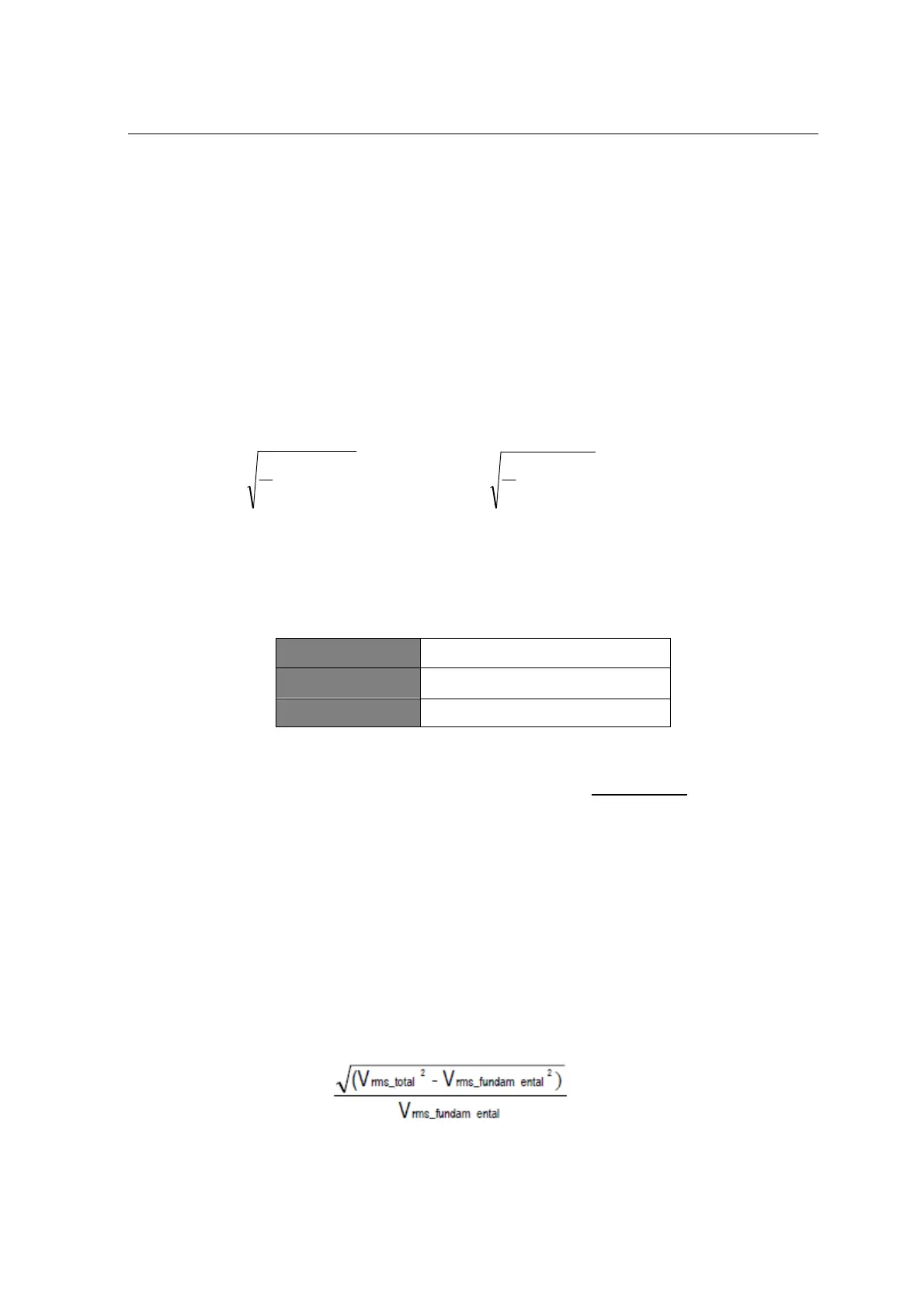
The THD measurement is done according below formula
voltage THD =