9.1.Standard RS-485 interface
206
External equipment
9
POINT
- The end of each cable should be stripped 7 mm.
- The terminal block terminal screw tightening torque is0.6 N·m.
7KHZLULQJFDEOHVVKRXOGEH$:*WR$:*
- The use of twisted pair cables is recommended for wiring.
- The S.G. of the standard RS-485 interface and the common terminal of the
internal circuit are shared.
- The S.G. terminal should be wired as required according to the communication
status between CSD-912B and the opposite unit.
- The S.G. terminal may not be provided depending of the host equipment, such as
a PC and or a sequencer.
- To conform CSD-912B to the CE mark applicable standards and the JIS
standards, wire a shielded cable wire to the F.G. terminal of the RS-485 interface
terminal block.
- The polarity of signals on the host side, such as a PC and a sequencer, may be
opposite.
9.1.3. Communication setting
7KHIROORZLQJLWHPVPXVWEHVHWDFFRUGLQJWRWKHVSHFL¿FDWLRQVRIWKHVWDQGDUG56
LQWHUIDFH
- Operation mode
- Baud rate
- Data bit length
- Parity
- Stop bit
- Terminator
- Decimal point addition
- Address
- Data delay time
- Target output of stream mode
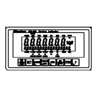
The communication settings of the standard RS-485 interface are set on the RS-485
communication setting screen. To display the RS-485 communication setting screen, tap
[BUILT-IN SERIAL I/F] on [MENU 1/2], and then tap [RS-485] on the standard
communication screen 1/1.
The standard communication setting screen will be displayed.
Tap [BUILT-IN
SERIAL I/F].