Installation
100
Mitel 415/430 as of R4.1
syd-0580/1.2 – R4.1 – 08.2016
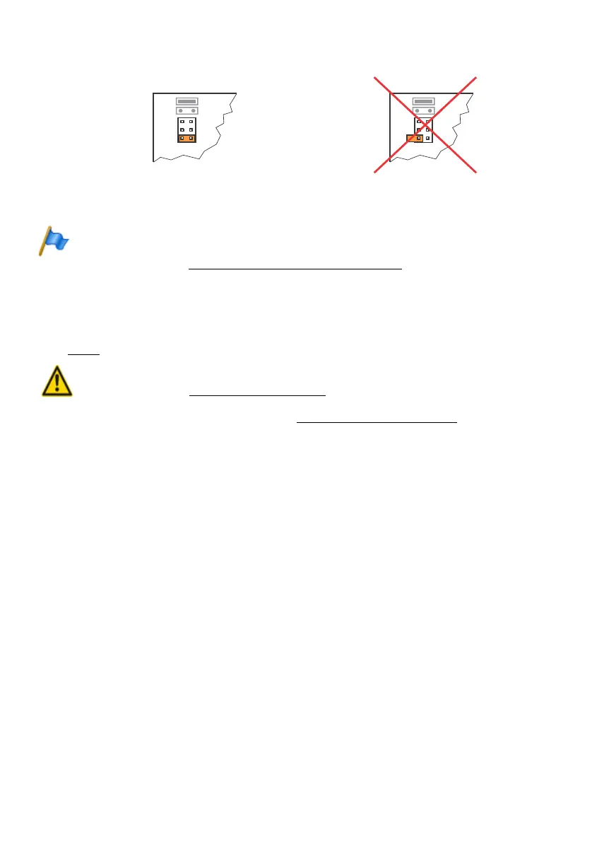
Fig. 24 Jumper position on ESST card
Note
Any incorrectly fitted or missing wiring adapters are signalled by a red flashing LED on the dis-
play after start-up (see "Wiring Adapter Malfunction Mode", page 205).
4. 5. 3 DSP module
DSP modules belong to the category of system modules and are fitted to the SM1 slot
(see Fig. 7
). Three DSP modules are stackable.
Warning
Be sure to observe the "Safety regulations", page 84.
1. Shut down the communication server (see "Shutdown Mode", page 206) and dis-
connect it from the power supply.
2. Remove the housing cover.
3. Remove the fastening screw from module slot SM1.
4. Instead of the fastening screw, screw in the spacer sleeve enclosed with the mod-
ule.
5. Place the module on slot SM1 of the communication server (or onto a module al-
ready fitted in that slot) and press down evenly on both connectors as far as the
stop.
6. Secure the module with the fastening screw.
7. Fit the housing cover.
8. Reconnect the communication server to the power supply.
4. 5. 4 Component mounting rules
The component mounting rules mentioned in the previous chapters are listed here in
an overview:
• In principle the interface cards can be used in all the card slots.
Exceptions:
N
N
N
N
S/
Jumper in
position T:
Jumper in
position S:
Card ESST-2
Card ESST-2
RIGHT
WRONG