Installation
115
Mitel 415/430 as of R4.1
syd-0580/1.2 – R4.1 – 08.2016
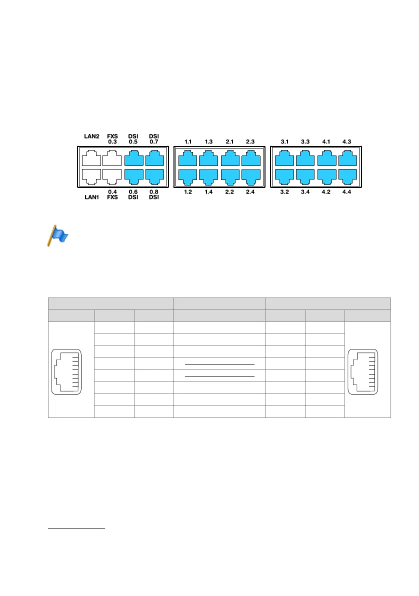
4. 7. 3. 1 DSI terminal interfaces
The DSI terminal interfaces of the mainboard (for Mitel 415 only 0.5 and 0.6) are per-
manently routed to the front panel and labelled accordingly. With the appropriate inter-
face cards and Wiring Adapters, additional DSI terminal interfaces can also be made
available at the RJ45 sockets 1.x...4.x (with Mitel 415 only 1.x and 2.x). The possible
RJ45 sockets are highlighted in colour in the figure below.
Fig. 41 Connection possibilities for DSI terminal interfaces
Note
Circuit type as per EN/IEC 60950: SELV
Connection
Tab. 50 Connection of DSI terminal interfaces
DSI bus configuration
Depending on the line length, 1 or 2 system phones of the MiVoice 5300
1)
series can
be connected on each DSI-AD2 interface. The following requirements apply with re-
gard to the bus length to ensure that the maximum permissible signal delay is not ex-
ceeded:
Communication server Cable cores Connection socket
Socket Pin DSI signal DSI signal Pin Socket
1– –1
2– –2
3– –3
4a a4
5b b5
6– –6
7– –7
8– –8
1) Office 10, Office 25, Office 35, Office 45/45pro are supported as before