Operation and Maintenance
193
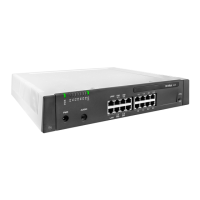
Mitel 415/430 as of R4.1
syd-0580/1.2 – R4.1 – 08.2016
Note:
The wiring adapter must also be changed to the corresponding slot. Any incorrectly fitted or
missing wiring adapters are signalled by a red flashing LED on the display after start-up (see
"Wiring Adapter Malfunction Mode", page 205).
2. Connect the system terminals to the ports of the new slot.
3. Reconfigure the port assignment.
4. In the WebAdmin view Cards and modules ( =4g) Confirm card in the new slot
and Delete it from the old slot. The configuration data at the old slot location is now
deleted.
Note:
Not all cards can be equipped on all slots (see "Component mounting rules", page 100).
6. 3. 4 System modules
The category system modules comprises the DSP modules stacked in slot SM1. DSP
modules are available in various versions (SM-DSPX1, SM-DSPX2, SM-DSP1, SM-
DSP2). Compared with DSP modules, modules with the designation DSPX are fitted
with more powerful DSP chips.
6. 3. 4. 1 Changing the DSP module
The following describes how to replace a DSP module if it is defective or how to re-
place it for a more powerful module.
To change a DSP module, proceed as follows:
Warning
Be sure to observe the "Safety regulations", page 84.
1. Carry out preparations (see "Preparations", page 189).
2. Remove the housing cover.
3. Remove the old or defective module by loosening the fastening screw and carefully
pulling the module out vertically of the module slot.
Note:
If there are several modules fitted and the card to be replaced is not topmost, the spacing
sleeves have to be loosened and the modules pulled. The order of the modules on the slot is
relevant only if different types of modules are equipped.
4. Press the new module downward evenly on both connectors to the stop.
5. Secure the module with the fastening screw.
6. Fit the housing cover.
7. Reconnect the system to the power supply.