Operation and Maintenance
200
Mitel 415/430 as of R4.1
syd-0580/1.2 – R4.1 – 08.2016
6. 4 Display and control panel
The display and control panel of the Mitel 415 and Mitel 430 communication servers on
the front panel consists of an LED display panel and a pilot key. It is used to indicate
operating states and carry out functions.
6. 4. 1 LED display
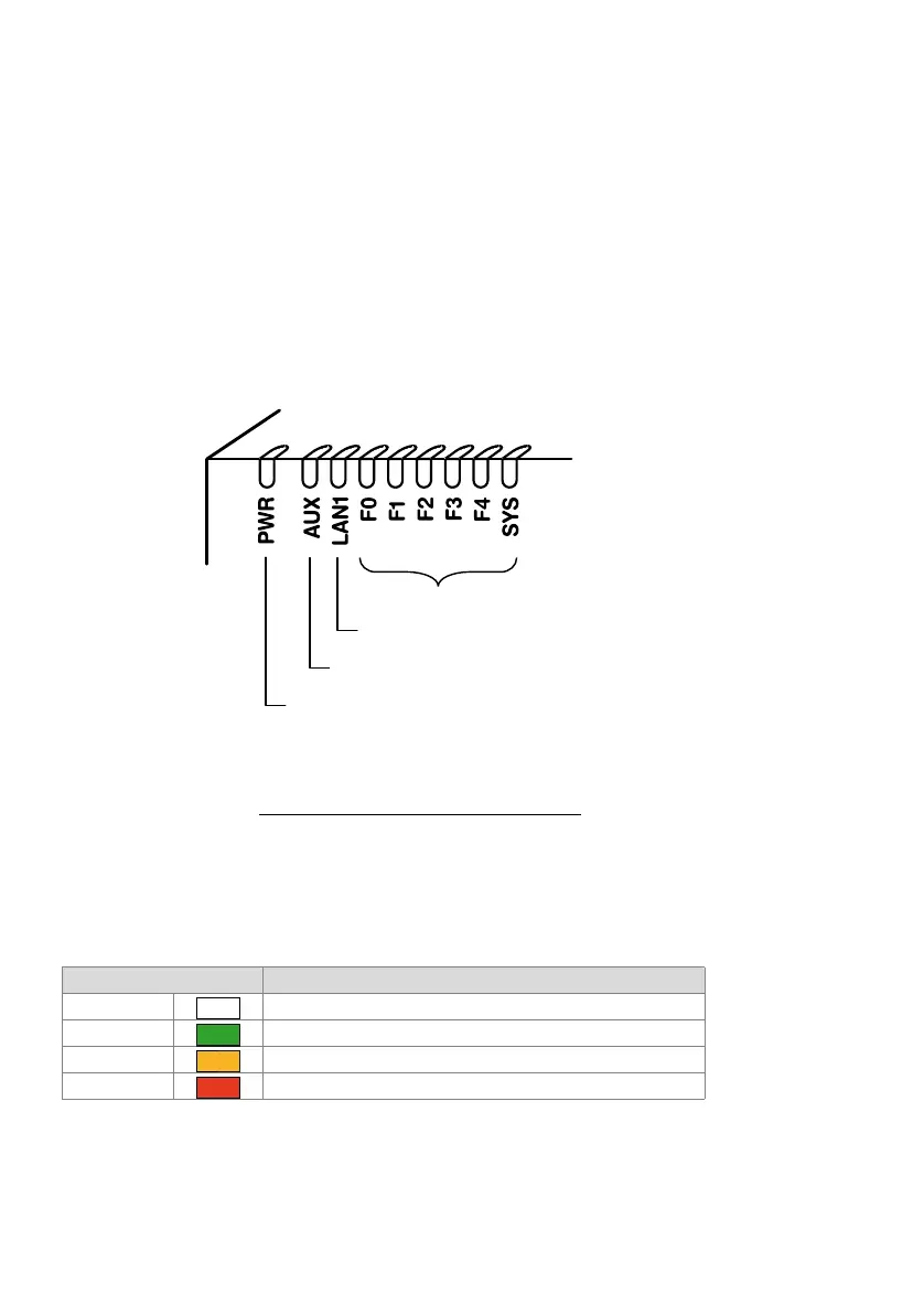
The front panel contains an LED display field with a total of 9 labelled LEDs. It is used
as an operating state and error indicator during the start-up phase and during opera-
tion.
"PWR" lit Power supply in order
"LAN1" lit: Port has a connection with the network
LAN1" blinking Port is receiving or sending data
"F0, F1, F2, F3, F4, SYS": see "
Operating modes and display priorities", page 202
Fig. 82 LED display
Each LED can take on one of four states: green (G), orange (O), red (R) and inactive.
In general the colours have the following meaning:
Tab. 87 Significance of the LEDs colours
An LED activation period lasts 1 second and is subdivided into 8 units of 125 ms. In
this way all the various flashing patterns can be displayed.
Colour Meaning
Inactive Switched off
Green Normal operation / everything in order
Orange Function is being carried out / is active
Red Warning / error
Power supply state
(For future expansions)
Ethernet state
Operating state and error display
–