Expansion Stages and System Capacity
40
Mitel 415/430 as of R4.1
syd-0580/1.2 – R4.1 – 08.2016
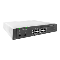
3. 2 Basic system
Mitel 415and Mitel 430 are based on the same basic system, they differ in terms of the
components fitted to the mainboard, the expansion possibilities and the system capac-
ities. The basic systems consists of the following components:
• Mainboard with front panel, screw covers and designation label integrated in metal
housing with detachable plastic cover
• Power supply unit with power cord
3. 2. 1 Interfaces, display and control elements
The following mainboard interfaces can be accessed only when the housing cover of
the communication server is open:
Tab. 13 Mainboard
The following interfaces, display and control elements of the mainboard are routed to
the front panel:
Tab. 14 Front panel
The diagram below shows the position of all the interfaces and slots on the mainboard
display and control elements and on the front panel.
Interfaces Mitel 415 Mitel 430 Designation / Remarks
Slots for interface cards 2 4 IC1...IC4 / with snap mechanism
Slots for system modules, type 1 1 1 SM1 / three system modules, stackable
Slots for system modules, type 2 – 1
1)
1) Not used at the moment
SM2
Slots for wiring adapters 2 4 WA1...WAx / one slot per wiring adapter
Slot for EIM card 1 1 EIM / card holder
Fan interface
2)
2) The fan is required only if the Mitel 430 is rack-mounted
– 1 FAN / 3-pin connector (Mitel 430 only)
Interfaces Mitel 415 Mitel 430 Note
DSI terminal interfaces 2 4 RJ45 socket
FXS terminal interfaces 2 2 RJ45 socket
Ethernet interfaces 10/100BaseT, half/full-duplex 2 2 RJ45 socket
RJ45 sockets on front panel, total 16 24 RJ45 socket
Audio input 1 1 3-pin jack socket
Supply input 1 1 2-pin supply socket
Pilot key 1 1
LED display 1 1