Installation
121
Mitel 415/430 as of R4.1
syd-0580/1.2 – R4.1 – 08.2016
Evaluation of an existing line installation
Line diameter: 0.5 mm
Loop resistance: 120 Ω
Fig. 43
indicates:
• Line length: 660 m
• Power available: 2120 mW
Cable Requirements
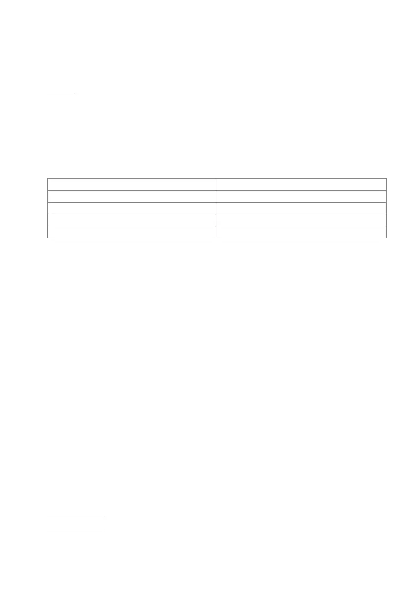
Tab. 53 Requirements for an DSI bus cable
Installation rules
• If an Mitel DECT radio unit is used, do not connect any other system phone to the
same DSI bus.
• Do not use any terminating resistors at the bus extremity.
• Avoid using different cable cross-sections on the same bus
• Use the supplied cables for connecting the system phones
• Cabling of AD2 terminals is restricted to pairs of a separate dedicated cable(s).
1)
.
Terminals
The following system terminals can be operated on the DSI-AD2 bus:
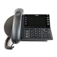
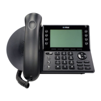
• MiVoice 5300 series system phones
2)
• Mitel DECT radio units
The system phones on an DSI-AD2 bus are addressed via a single-digit terminal selec-
tion digit (TSD).
Example:
The address of a system phone with TSD 2 on DSI interface 3.5 is 3.5-2.
Core pairs
×
cores 1
×
2 o 1
×
4
Stranded yes
1)
1) Note: max. 25 m can be crossed unstranded.
(CH: Applies also to cable type G51)
Wire diameter, core 0.4…0.6 mm
Screening recommended
Characteristic impedance < 130
Ω
(1 MHz)
1) Applies in Australia only
2) Office 10, Office 25, Office 35, Office 45/45pro are supported as before