Installation
142
Mitel 415/430 as of R4.1
syd-0580/1.2 – R4.1 – 08.2016
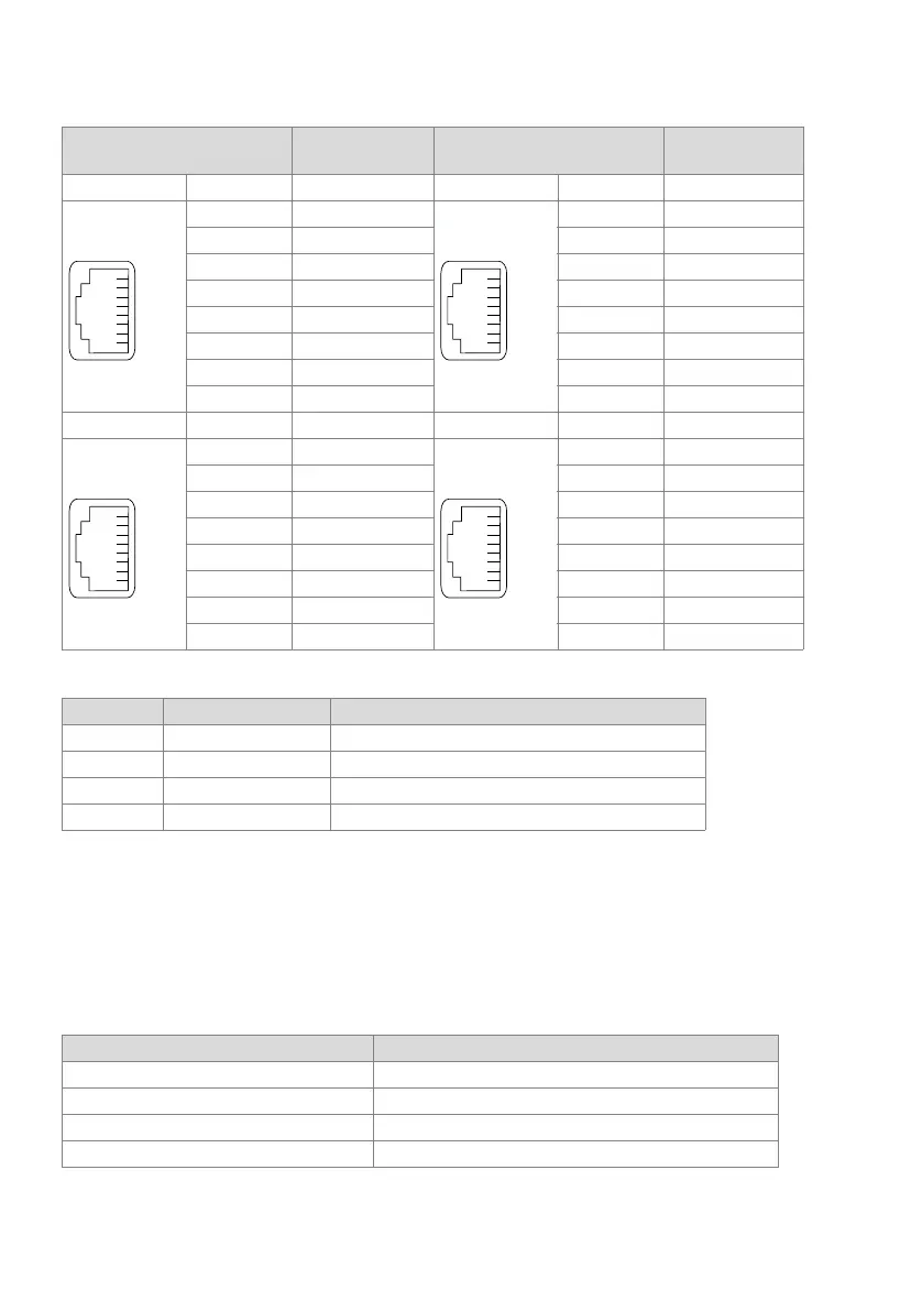
Tab. 68 Connection in slot IC1 (Mitel 415) or slot IC1, 2 or 3 (Mitel 430)
Tab. 69 Connections of control inputs and outputs
Freely connectable relay contacts
The two freely connectable relay contacts can be used to control external devices or
equipment such as heating, alarm or outdoor lighting systems (possibly via external re-
lay for 115/230 VAC).
There are no special requirements for the cables.
Tab. 70 Relay operating data
RJ45
Communication
server
RJ45
Communication
server
Socket X1 Pin Signal Socket X3 Pin Signal
1– 1–
2– 2–
3O1-1 3 –
4O2-1 4 –
5O2-2 5 –
6O1-2 6 –
7– 7–
8– 8–
Socket X2 Pin Signal Socket X4 Pin Signal
1– 1–
2– 2–
3I3-1 3 –
4I4-1 4 –
5I4-2 5 –
6I3-2 6 –
7– 7–
8– 8–
IO port Signal Function
1 O1-1, O1-2 Floating contact, relay 1
2 O2-1, O2-2 Floating contact, relay 2
3 I3-1, I3-2 Control input 1
4 I4-1, I4-2 Control input 2
Parameter Value
Number of changeover switches per relay 1
Insulation between the changeover switches 0.5 kV
Type of contact no (normally open, NO contact, make contact)
max. contact loading 24 VDC, 30 VAC, 1 A