PTS 400.3 PLUS Operation Manual_R02 Page 153/306
Parameter settings for burden measurement I
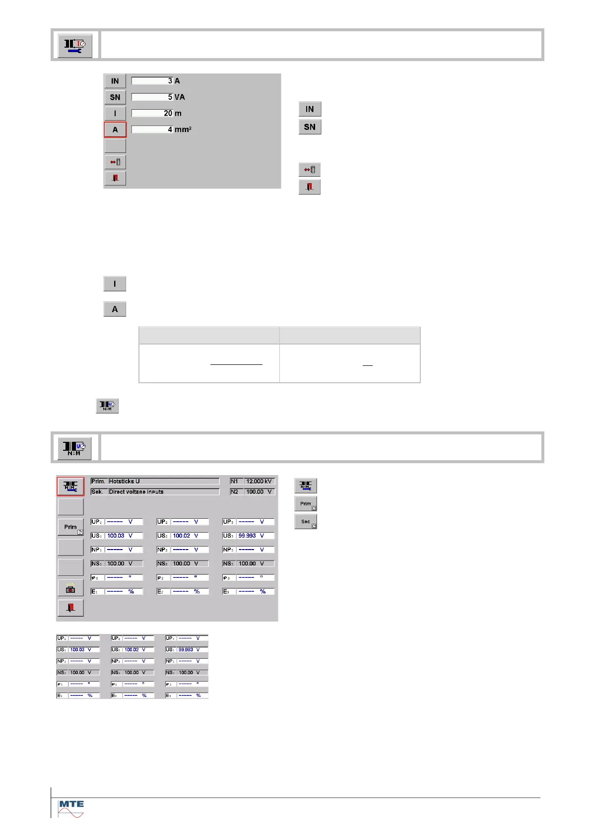
To perform the measurement, the nominal values
of the current transformer (CT) must be entered:
Rated secondary current in A
This information can be found on the name plate
or the calibration certificate of the transformer.
Exit, back to calling menu
If the burden voltage cannot be measured directly at the secondary side of the current
transformer, the influence of the wires between measuring point and transformer and the
influence of junctions to the total burden can be regarded by entering values at l, A. The
entries are regarded for the calculation of Rl and Sn.
The entries l, A are optional and should be set to zero, if not used.
Total length of conductor from measuring point to current transformer and back to
measuring point in m.
Cross section of conductor between measuring point and current transformer in
mm
2
.
Resistivity of copper ()
8.6.3 Voltage transformer (PT) ratio measurement
Voltage transformer ratio
Reference for voltage ratio calculation
Definition of the reference NP or NS.
Display of measured primary and secondary val-
ues
φ Phase angle in °
Error E of the measured ratio / nominal ratio in %.
Display of results
• Measured primary voltage UP and secondary voltage US.
• Calculated nominal values NP or NS based on ratio UP-
rim/USec, depending on the value that is defined as refer-
ence.
• φ Phase angle in °
• Error E of the measured ratio / nominal ratio in %
The results are updated in the interval of the time base T (e.g.
1s).
 Loading...