PTS 400.3 PLUS Operation Manual_R02 Page 155/306
Call storage of test results menu [10].
Exit, back to calling menu
8.6.4 Current transformer (CT) ratio measurement
This function is used to measure the transformer ratio of current transformers. Three current trans-
formers can be measured at the same time, because the reference meter has six current input chan-
nels. The kind of current measurement, direct or with clamp-on current transformers, can be selected
for primary and secondary input. Both primary and secondary current can be measured with current
clamps. This makes it possible to test instrument transformers during normal measuring equipment
operation without any shutdowns or safety disconnections.
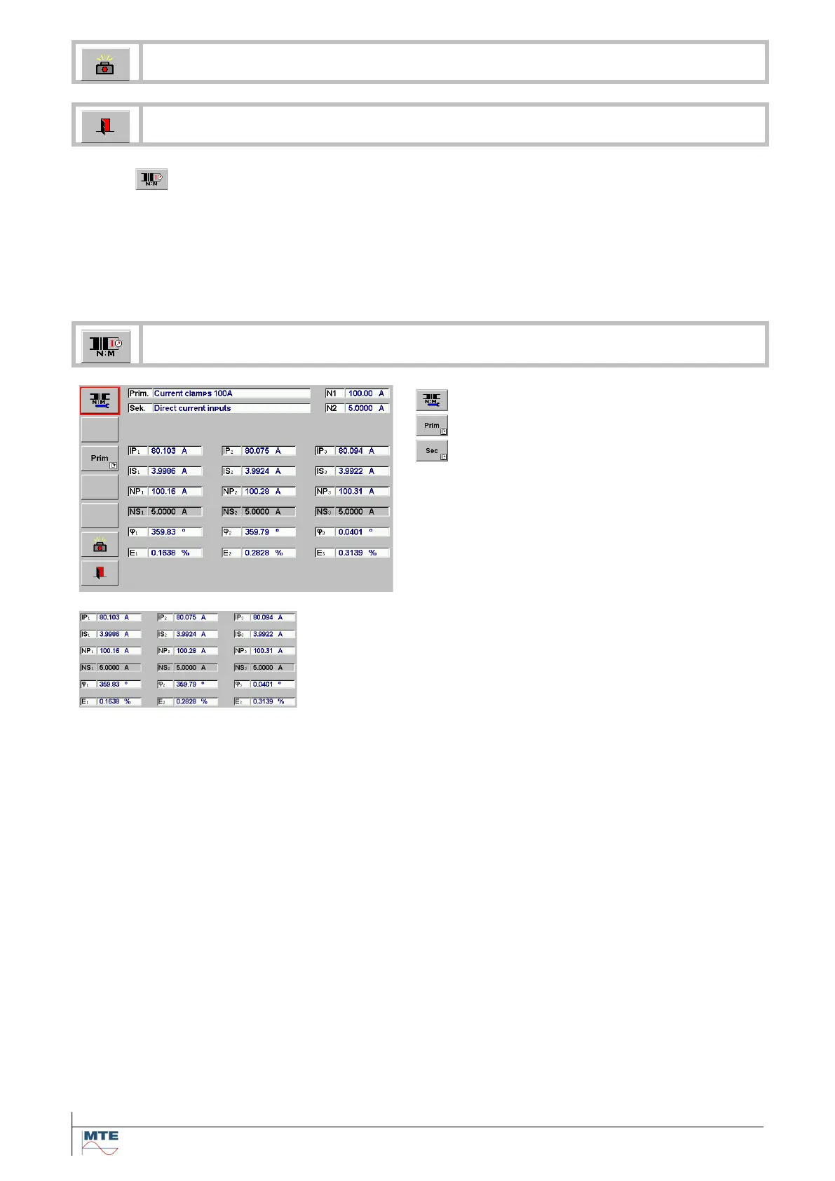
Current transformer ratio
Reference for current ratio calculation
Definition of the reference
Display of measured primary and secondary val-
ues
φ Phase angle in °
Error Ex of the measured ratio / nominal ratio in %
Display of results
• Measured primary current IP and secondary current IS.
• Calculated nominal values NP or NS based on ratio
IPrim/ISec, depending on the value that is defined as ref-
erence.
• φ Phase angle in °
• Error E of the measured ratio / nominal ratio in %
The results are updated in the interval of the time base T (e.g.
1s).
Nominal ratio
r
n
= NP
n
/NS
n
Measured ratio
r = IP/IS = NP/NS
Ratio error
E = [r/r
n
–1]*100 [%]
Input of nominal ratio
To calculate the ratio error E the specified ratio of the trans-
formers must be defined. This is done by input of primary nom-
inal value NP and secondary nominal value NS or nominal ra-
tio at NP with NS = 1.
The fields of the reference are grey marked and will be the
base value for the calculation of NP or NS in the results display
section.