PTS 400.3 PLUS Operation Manual_R02 Page 299/306
PRS 600.3
18.2.1 Calculation formulae
All calculations are based on 16 bit samples of the phase voltages u1, u2, u3 and of the phase cur-
rents i1, i2, i3. The 6 values are simultaneously sampled at a rate of 31.25 kHz. Every sample is cor-
rected in amplitude and phase before further calculations are carried out. The correction parameters
used have been determined during manufacture and are stored in the internal non-volatile memory.
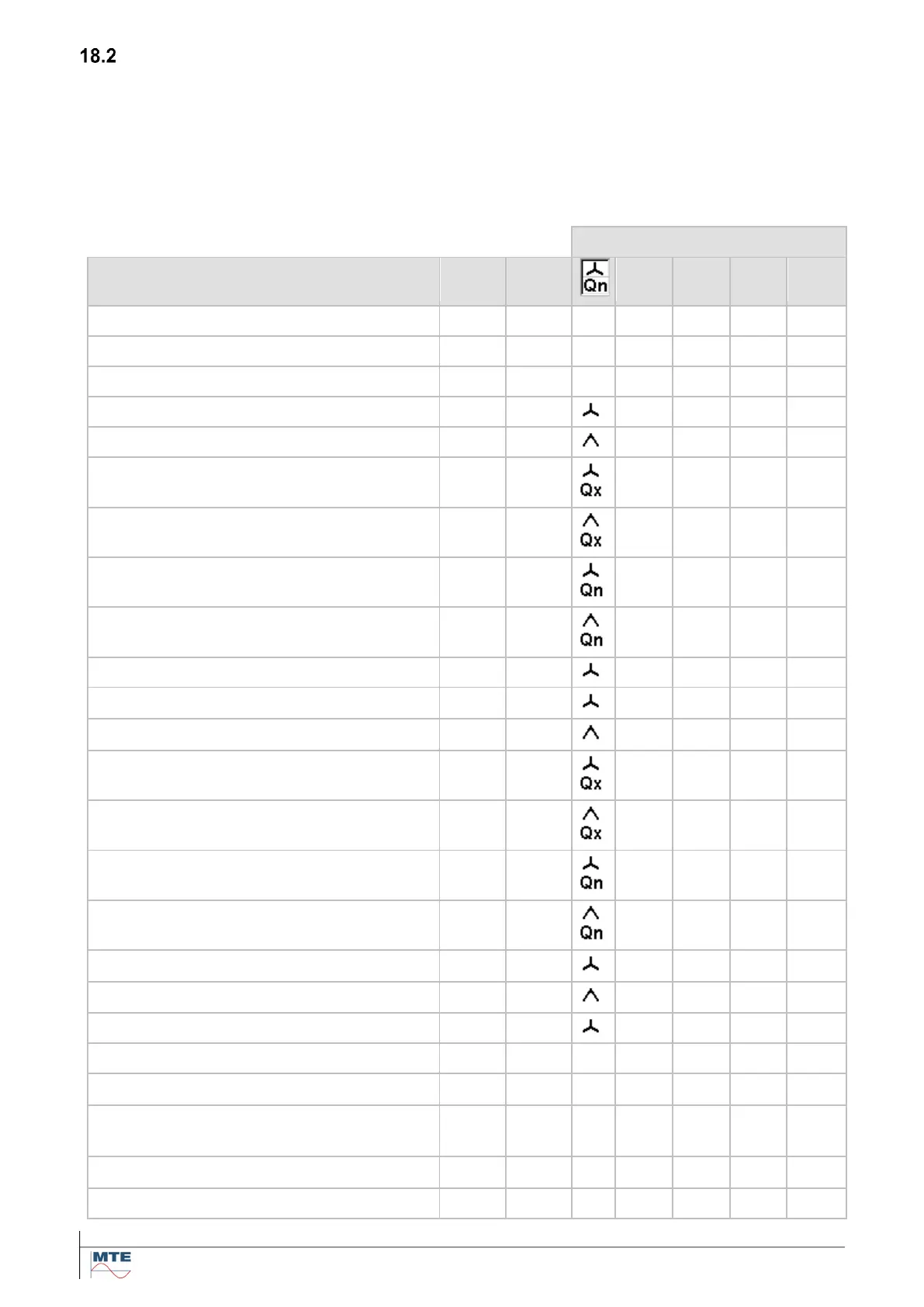
Table 18-1 Definition of basic measured variables
Indications on instrument
Reactive power, artificial, 4-wire
Reactive power, artificial, 3-wire
Reactive power, natural, 4-wire
Reactive power, natural, 3-wire
Total active power 4-wire
Total active power 3-wire
Total reactive power, artificial, 4-wire
Total reactive power, artificial, 3-wire
Total reactive power, natural, 4-wire
Total reactive power, natural, 3-wire
Total apparent power 4-wire
Total apparent power 3-wire
Power factor per phase 4-wire
Total power factor 4-wire / 3-wire
Angle between current and voltage
Angle between voltage and voltage
Angle between current and current