PTS 400.3 PLUS Operation Manual_R02 Page 150/306
Assign results to phase L1, L2, L3
Select L1, L2, L3 to assign the measured results (U1, I1) to the corresponding phase (cy-
clical mode).
The calculated results are indicated with the index of the selected phase. This function
can be used to test a 3-phase meter phase by phase and save the results.
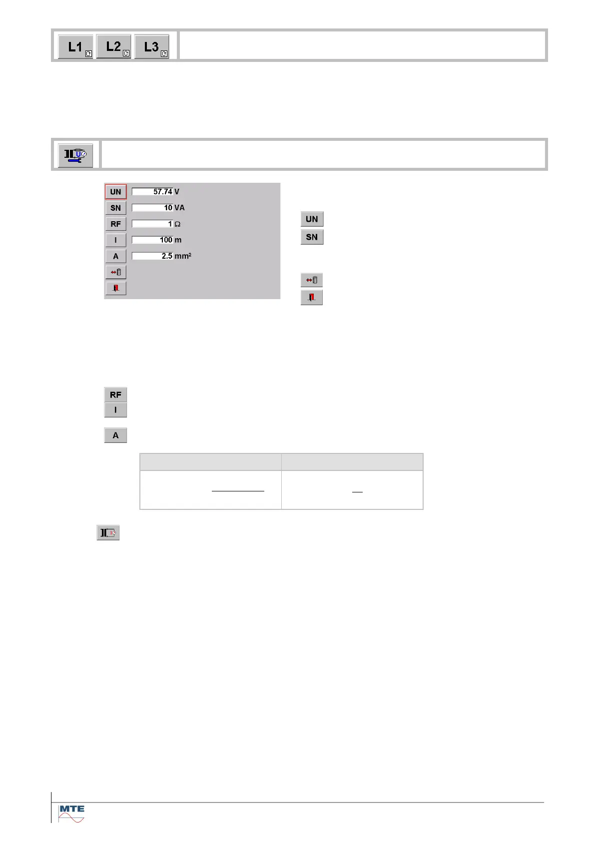
Parameter settings for PT burden measurement
To perform the measurement, the nominal values
of the potential transformer (PT) must be entered:
Rated secondary voltage in V
This information can be found on the name plate
or the calibration certificate of the transformer.
Exit, back to calling menu
If the voltage cannot be measured directly at the secondary side of the voltage trans-
former, the influence of the wires between measuring point and transformer and the influ-
ence of fuses and junctions to the total burden can be regarded by entering values at l, A
and RF. The entries are regarded for the calculation of Rl and Sn.
The entries l, A and RF are optional and should be set to zero, if not used.
Resistance of fuses and junctions between measuring point and transformer in .
Total length of conductor from measuring point to voltage transformer and back to
measuring point in m.
Cross section of conductor between measuring point and voltage transformer in
mm
2
.
Resistivity of copper ()
8.6.2
Current Transformer (CT) burden measurement
The rated secondary current (IN) and rated burden (SN) of the current instrument transformer must
be entered.
Optionally the influence of the wires between secondary side of the transformer and the measuring
point can be regarded by entering length (l) and cross section (A) of the wire.
The instrument measures the actual secondary current (I), the burden voltage (U) and the burden
factor (cos).
As main result the ratio (Sb) of total rated operating burden (Sn) to rated burden (SN) is calculated
and indicated in %.
Regarding the international standard IEC 60044-1 the Sb value should be in the range:
25 % SN Sb 100 % SN
After the exchange of a mechanical meter with an electronic meter in a substation the burden of the
current measurement transformer is often too low and measures must be taken to raise the burden to
be in the admissible range again.
For the necessary connections between transformer and instrument see the connection example in
chapter [17.2.11].
 Loading...