PTS 400.3 PLUS Operation Manual_R02 Page 149/306
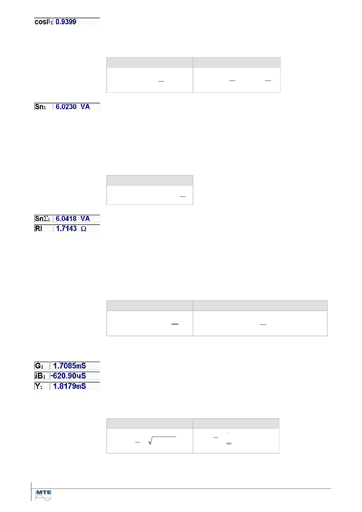
Burden factor
Ratio of real part (G) to admittance (Y). The value is calculated based on
the measured values U and I.
=
=
−−
G
B
tan
Y
G
cos
11
Rated operating burden
Burden related to the rated voltage, calculated with the measured admit-
tance (Y) and the entered rated voltage (UN). This value can directly be
compared with the rated burden specified by the manufacturer (SN). Be-
cause the calculation of SN is based on the admittance (Y), the measure-
ment is independent of the actual secondary voltage (U). The secondary
voltage (U) can be different from the rated value (UN). The result remains
the same.
Total rated operating burden
Resistance of wire, fuse and junctions
Burden related to the rated voltage with regard of voltage drops between
secondary connections of the voltage transformer and the measuring point
of the secondary voltage (U).
The voltage drop is calculated with the optional entries for length (l) of wire
from measuring point to transformer and back and cross section (A) of the
wire. The entered value RF for fuse and junctions will be regarded addi-
tionally.
Resistance of wire, fuse and junctions
If RF, A and l are zero: Sn = Sn
Conductance (real part of Y)
Susceptance (imaginary part of Y)
The admittance (Y) and its real part (G) and imaginary part (jB) are calcu-
lated based on the measured values U and I.
 Loading...