PTS 400.3 PLUS Operation Manual_R02 Page 210/306
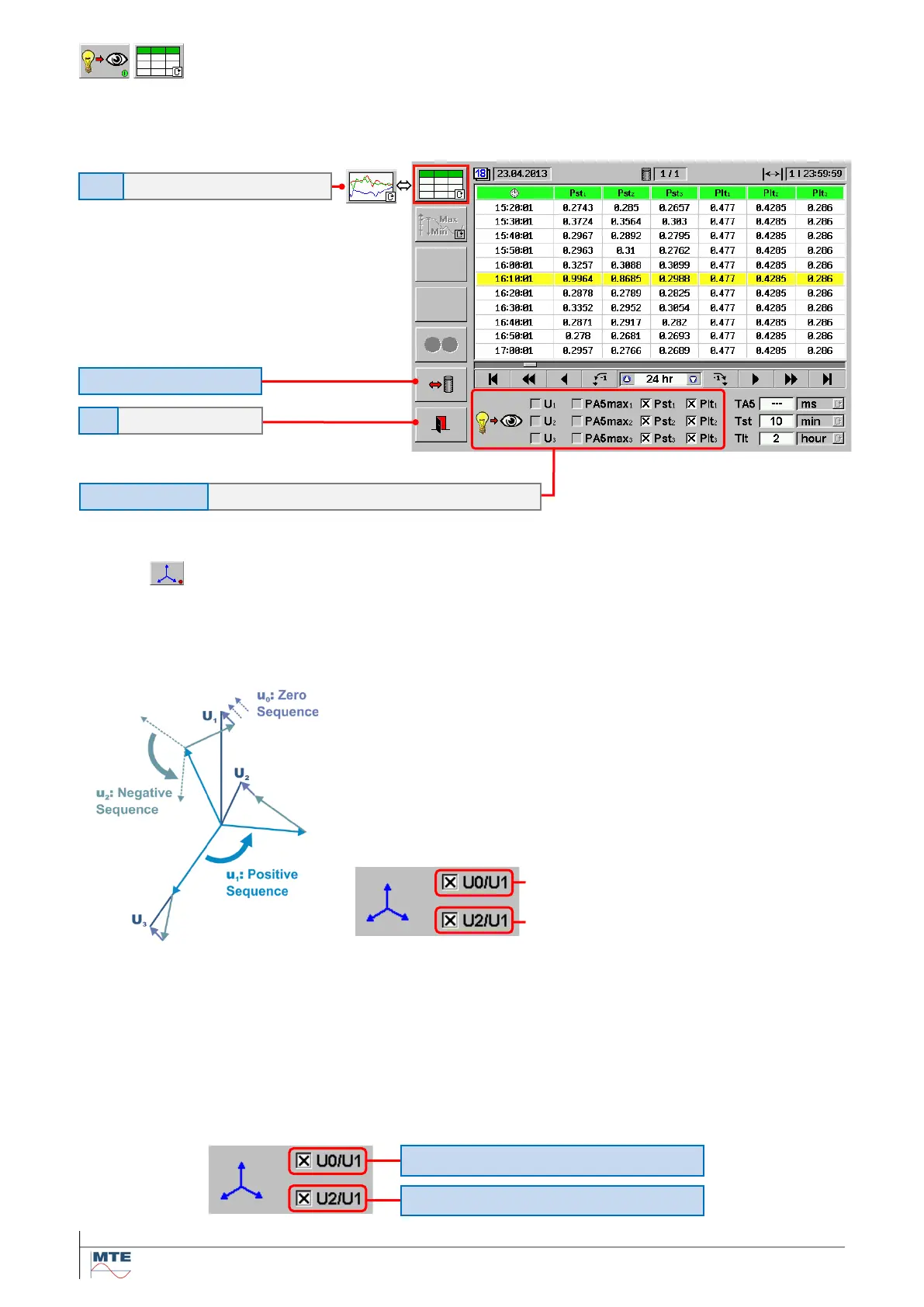
Flicker table view
Example 1: Analysis of recorded short and long term flicker of phases 1, 2, 3.
12.1.5
Unbalance
The voltage unbalance is only relevant in 3 phase systems and is caused by unequal impedances
and asymmetrical loads. It causes problems mainly in distribution networks and e.g. can reduce the
power and shorten the lifetime of motors and transformers.
The unbalance is analysed with help of the system of symmet-
rical components, which breaks down an unbalanced system in
three balanced systems:
- Positive sequence (u
1
)
- Negative sequence (u
2
)
- Zero sequence (u
0
)
The unbalance is indicated in relation to the positive sequence
component (u
1
).
At a balanced 3 phase system the phase angles between the voltages are 120° and the voltage val-
ues are equal. For a perfectly balanced system therefore both zero and negative sequence unbal-
ance are zero.
The negative sequence unbalance (U2/U1) is more important.
Typical limit for negative sequence unbalance regarding EN 50160: U2/U1 ≤ 2 %
Selectable Values
Zero sequence unbalance [%]
Negative sequence unbalance [%]
Short and long term flicker of voltages U1, U2, U3
Zero sequence voltage unbalance factor [%]
Negative sequence voltage unbalance factor [%]