PTS 400.3 PLUS Operation Manual_R02 Page 33/306
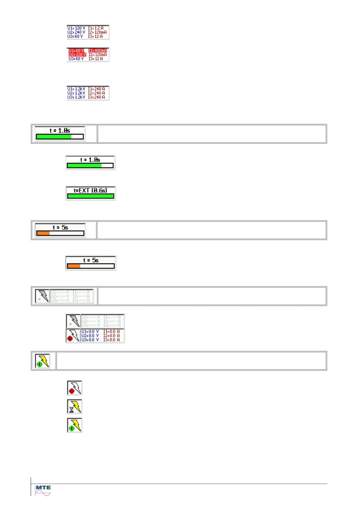
Normal display
The actual selected end of range value is indicated for each phase
to neutral voltage (U1, U2, U3) and each phase current (I1, I2, I3).
Range overflow
The range indication of inputs, which are overloaded are blinking
between red and normal and a repeating beep can be heard.
The overload indications disappear as soon as normal conditions
are reached again.
Transformer factors activated
The internal selected end of range values 120V and 12A are multi-
plied with the defined transformer factors (e.g. voltage 1kV:100V =
10, current 100A:5A = 20).
Time base of reference standard
Internal time base interval
The set time base is indicated. The bar graph shows the actual
elapsed time of the running interval.
External control of time base interval
The time base interval is defined by impulses at impulse input 1.
The time in brackets indicates the time between the last two im-
pulses at input 1. The Indicated bar graph of the next period is
based on this value.
Internal time base interval
The set basic time base for PQ online measurement is shown.
The bar graph shows the actual elapsed time of the running inter-
val.
Source OFF indicated with red OFF button and white flash symbol
Source switch on / switch off active indicated with sandglass and yellow
blinking flash symbol. The set values are ramped up or down.
Source On indicated with green ON button and yellow flash