PTS 400.3 PLUS Operation Manual_R02 Page 88/306
Settings of phase sequence depending on network type
Settings input in Load point UIφf menu
Settings of source in load point menu
Settings for 1-phase 3P3W mode
Operational mode for testing 3-phase 3-wire electricity meters
Devices under test should be connected using phases L1, L2, L3
The settings for currents and the phase angle between voltages and currents are set via
the Load point UIφf menu. The current path L2 is switched off. The L1 and L3 current
paths may also be switched off manually.
Settings input in Load point UIφf menu
Settings of source in load point menu
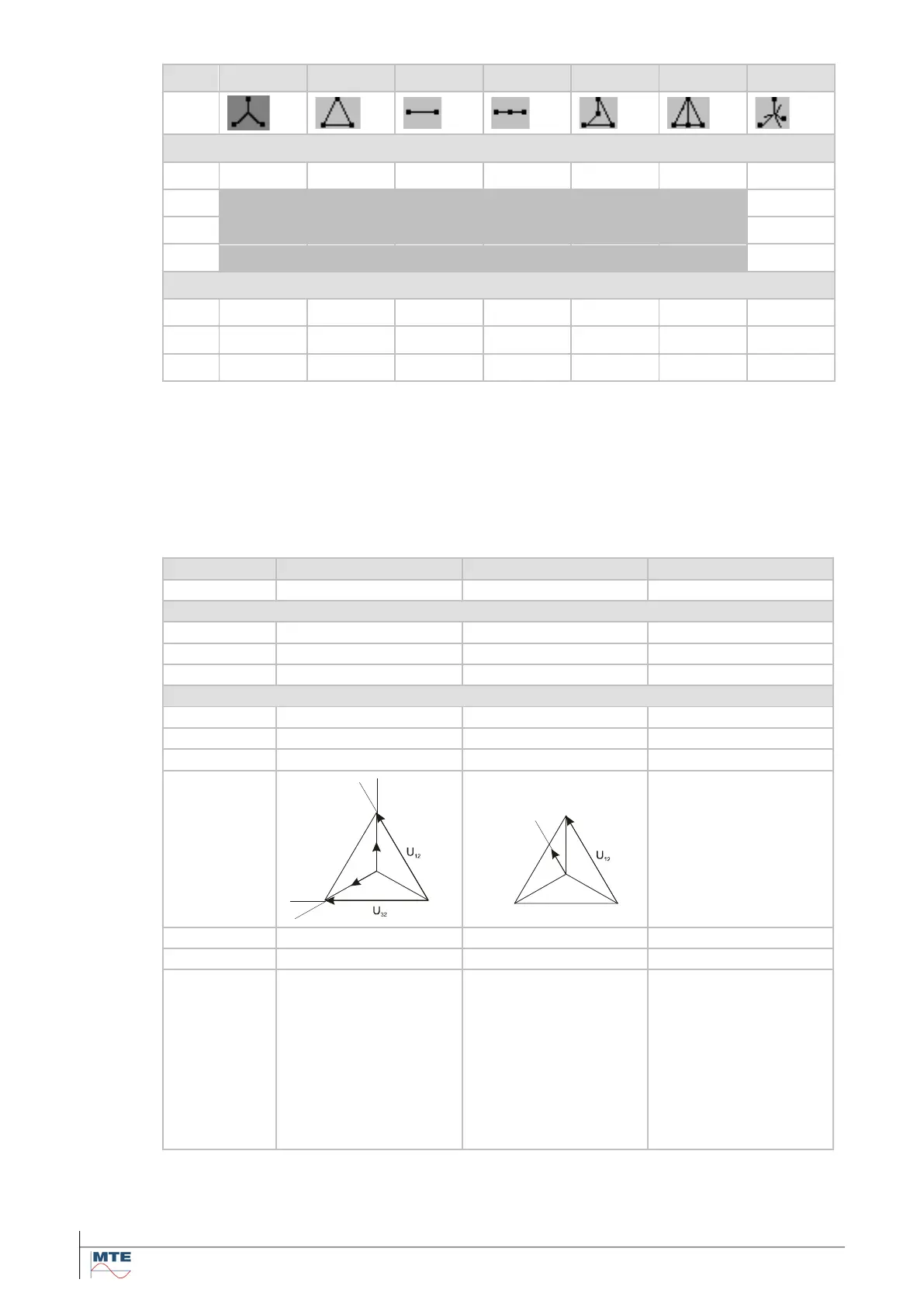
In the balanced 3-wire
mode a phase angle
setting of = 0°
causes a 30° shift be-
tween current and
voltage path of the
Aron circuitry.
In the unbalanced,
single sided 3-wire
mode the system op-
erates as in the 1-
phase mode. There-
fore, the current and
the associated volt-
age are in phase if the
setting is = 0°.
In the unbalanced,
single sided 3-wire
mode the system op-
erates as in the 1-
phase mode. There-
fore, the current and
the associated volt-
age are in phase if
the setting is = 0


 To Next Page