MultiSmart Installation & Operation Manual
14.11.2 Example: How To Make a Digital Output State Follow a Digital Input State
In this example, Digital Output 5 is configured to follow Digital Input 1.
• Select Advanced, select IO Module
Unit
• Select the Unit (e.g. Unit 01) then
• Select which board the digital output is located on (e.g. Top Board) then
• Select Digital Output then
• Select the free digital output that is to follow the digital input (e.g. DOUT 05) then
• Select Source and press “Use this button to view or change value”
• Select IO
Unit
• Select the Unit (e.g. _1) then
• Select which board the digital input is located on (e.g. Top Board) then
• Select Din
• Select the digital input that that the digital output is to follow (e.g. _1)
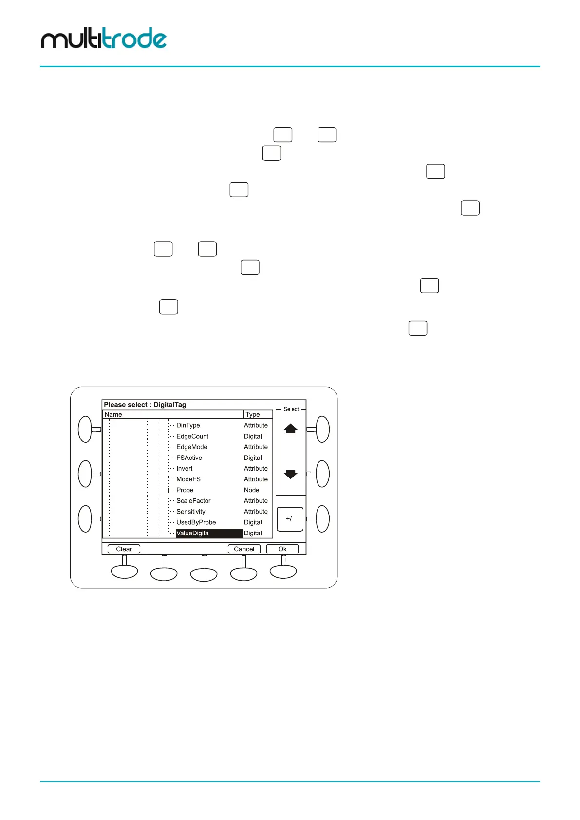
• Select ValueDigital (a digital tag) then press the Ok button
• Press the Save button
Figure 128 – Making a Digital Output Follow a Digital Input
Page 134 of 260 MultiSmart_IO_Manual_R20