MultiSmart Installation & Operation Manual
The MultiSmart pump station manager has up to four boards plugged into it depending on the application.
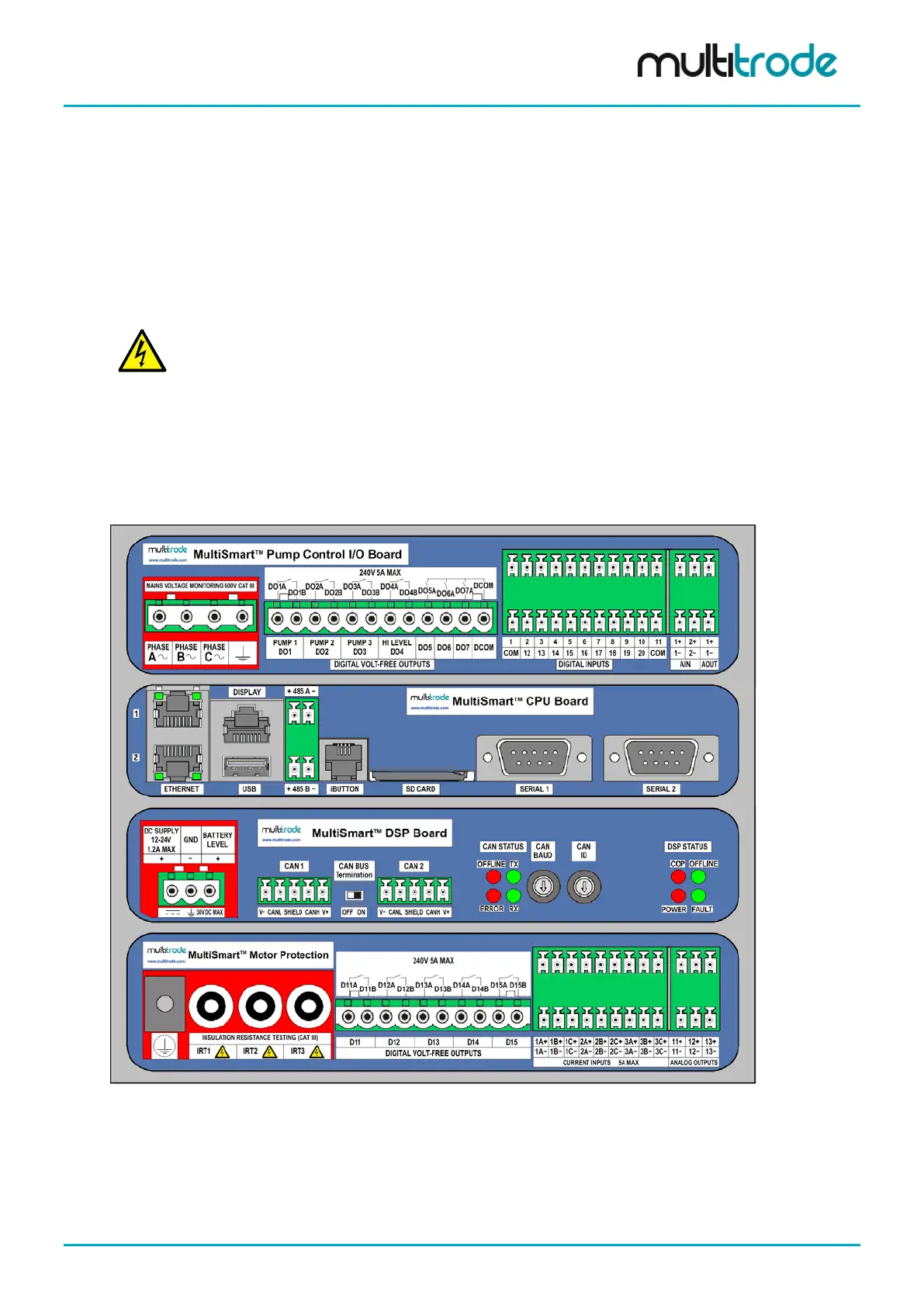
The most common configuration is shown below.
Pump Control I/O Board (3PC) - The pump control board monitors the single or 3-phase supply and
provides digital and analog I/O. Level sensing can be from a MultiTrode conductive probe or any 4-20mA
device (e.g. pressure transducer, ultrasonic device). Pump faults can be contact closures or pump specific
inputs such as seal, PTC thermistor or Flygt FLS and CLS. Digital outputs drive the pump contactors. (I/O =
20 x DIN, 2 x AIN, 7 x DOUT, 1 x AOUT)
CPU Board - Houses the microprocessor running the MultiSmart unit, provides two Ethernet ports, two
RS232 ports, two RS485 ports, an iButton (security key) port, connects to the display, and has SD card and
USB ports.
WARNING:
THE DIGITAL INPUTS ARE VOLT-FREE INPUTS. DO NOT APPLY ANY SOURCING VOLTAGE TO THEM.
DSP Board
This board handles the I/O and communicates between multiple I/O Module modules.
Energy Monitoring and Motor Protection (3MP)
Monitors single or 3-phase motor currents direct from a CT, and provides motor protection and power
monitoring. The board also carries out an automatic 1000VDC insulation resistance test of the motor
windings (I/O = 9 x IIN, 3 x IRT, 3 x AOUT, 5 x DOUT).
Figure 32 – MultiSmart Boards
MultiSmart_IO_Manual_R20 Page 37 of 260