MultiSmart Installation & Operation Manual
7.5.3 Add PSU & Battery Backup
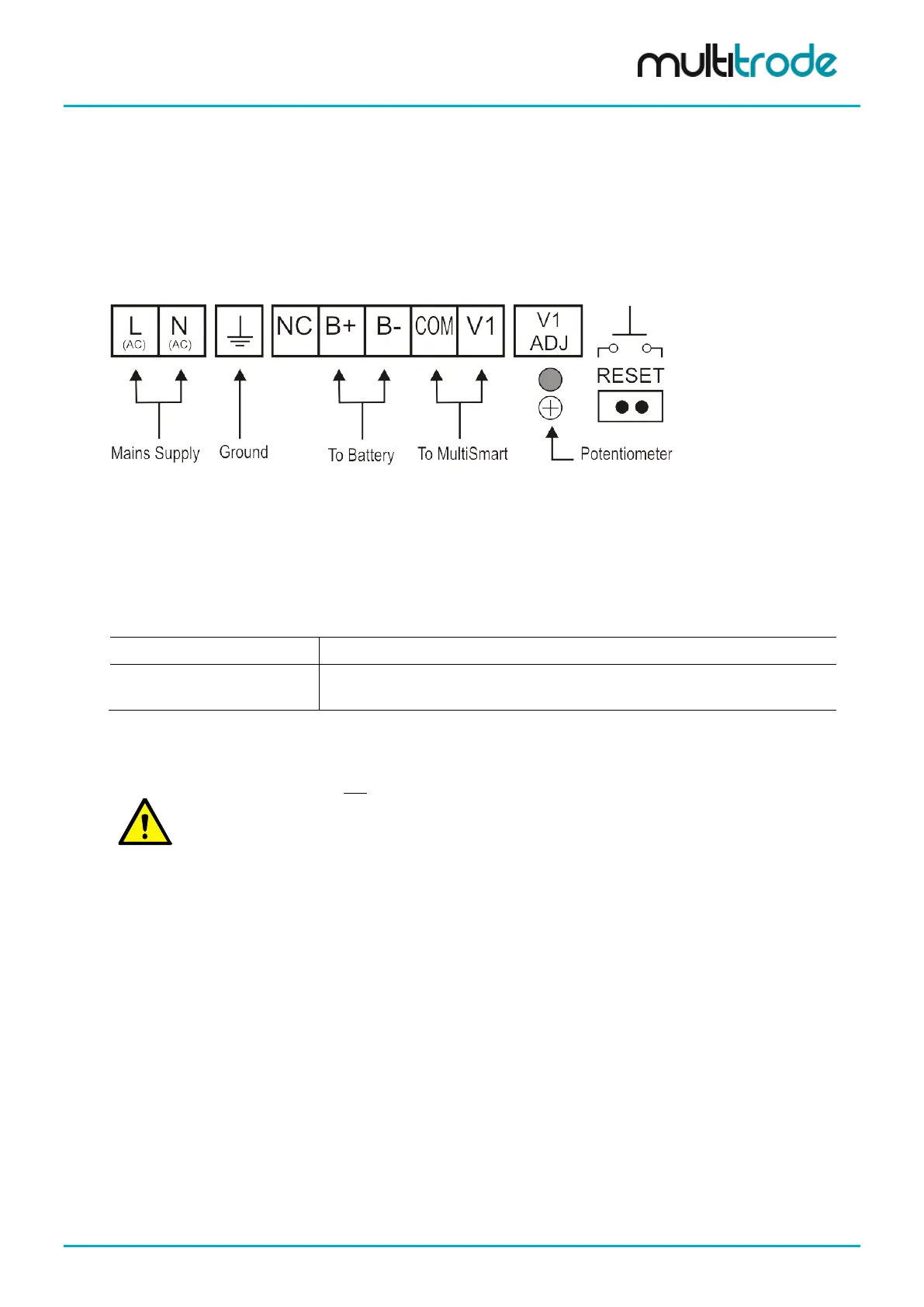
7.5.3.1 Connections to the Power Supply
The figure below illustrates the connections to the Mean Well power supply, model AD-155A, (Part No. PSU-
BATT-02).
Figure 51 – Power Supply Terminal Block Connections
7.5.3.2 Setting the Correct Charge Voltage
To help maximize battery life, it is essential that the correct charge voltage from the power supply to the
battery is set. The correct value is 13.7VDC +/- .1VDC*.
* This value applies to the current 12VDC, 28Ah batteries supplied (Yuasa and Panasonic brands - alternative brands
may be supplied, however).
To verify the charge voltage:
Measure the voltage between terminals B+ and B-
To alter the charge voltage:
Adjust the small potentiometer (labelled V1 ADJ) until the correct value is
displayed.
7.5.3.3 Power Supply Reset
NOTE:
If mains power is lost and the connections to the battery are removed and then reconnected, it will
be necessary to reset the power supply in order to restore operation (unless mains power is also
restored).
The reset connector is located on the right hand side of the terminal connections on the power
supply (labelled "RESET"). Bridge the two terminals within the reset connector to reset the power
supply.
MultiSmart_IO_Manual_R20 Page 51 of 260