UNIVERGE SV8100 Issue 4.1
System Hardware Manual 3 - 43
2.7.4.1 Connector Pin-Out on the PZ-BS10/PZ-BS11
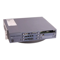
2.7.4.2 Install the PZ-BS10 Expansion Base Blade in the CHS2U
Controlling Chassis
1. Ensure the chassis is powered down.
2. Locate the door positioned on the left end
(expansion bay) of the Controlling Chassis.
Table 3-1 PZ-BS10/PZ-BS11 Connector Pin-Out
RJ-61 Cable Connector
PZ-BS10 – CN2, CN3, CN 4
PZ-BS11 – CN3
Pin No. Connection
1HW_UP (+)
2HW_UP (-)
3HW_DWN (+)
4FS (+)
5FS (-)
6 HW_DWN (-)
7 CK8M (+)
8 CK8M (-)
Figure 3-48 PZ-BS10 Expansion Bay in Controlling Chassis

 Loading...