System Hardware Manual 2 - 1
Chapter
2
SV8100 System Specifications
SECTION 1 GENERAL INFORMATION
This chapter provides detailed specifications for the SV8100 system
technician. The technician should review this information carefully before
installing the system.
SECTION 2 SYSTEM BLOCK DIAGRAM
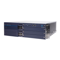
Figure 2-1 SV8100 System Block Diagram shows the Blades that can be
installed in the chassis and the number of channels supported when the
Blade is installed. Table 2-1 List of Abbreviations lists abbreviations used
in the diagram.
Table 2-1 List of Abbreviations
Abbreviation Description
ACD Automatic Call Distribution
ADA Analog Recording Adapter
APR Analog Port Adapter (with ringer)
BCH Bluetooth Cordless Handset
BHA Bluetooth Hub Adapter
AUX IN/OUT BGM/MOH Port (on CPU)
BRI Basic Rate Interface
BRIDB Expansion Basic Rate Interface Blade on BRI
BRT Basic Rate Interface Blade/ISDN Terminal Interface Blade
BUS0 BUS Interface Blade (for 1U chassis)
BUS1 BUS Interface Blade (for 2U chassis)
CCT CCIS Interface Blade
CF Compact Flash
CFT Conference Trunk (on CPU)

 Loading...


