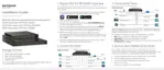
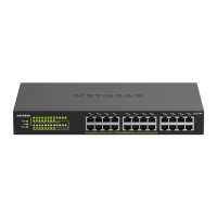
S350 Series 24-Port (PoE+) and 48-Port Gigabit Ethernet Smart Managed Pro Switches
Configure Switching User Manual118
The System Information page displays.
5. Select Switching> LAG > Basic > LAG Configuration.
6. In the LAG Name field, enter a name for the LAG.
You can enter any string of up to 15 alphanumeric characters.
7. In the Description field, enter the description string to be attached to a LAG.
The description can be up to 64 characters in length.
8. From the Admin Mode menu, select Enable or Disable.
When the LAG is disabled, no traffic flows and LACPDUs are dropped, but the links that
form the LAG are not released.
The default is Enable.
9. From the Hash Mode
menu, select the load-balancing mode for a port channel (LAG):
• 1 Src MAC, VLAN, EType, incoming port. This mode uses the source MAC
address, VLAN, EtherType, and incoming port that are associated with the packet.
•
2 Dest MAC, VLAN, EType, incoming port. This mode uses the destination MAC
address, VLAN, EtherType, and incoming port that are associated with the packet.
•
3 Src/Dest MAC, VLAN, EType, incoming port. This mode uses the source and
destination MAC addresses, VLAN, EtherType, and incoming port that are associated
with the packet.
This is the default mode.
• 4 Src IP and Src TCP/UDP Port Fields. This mode uses the source IP address and
source TCP or UDP port value that are associated with the packet.
•
5 Dest IP and Dest TCP/UDP Port Fields. This mode uses the destination IP
address and destination TCP or UDP port value that are associated with the packet.
•
6 Src/Dest IP and TCP/UDP Port Fields. This mode uses
the source and destination
IP addresses and source and destination TCP or UDP port values that are associated
with the packet.
Note: The switch balances traffic on a port channel (LAG) by selecting one of
the links in the channel over which packets must be transmitted. The
switch selects the link by creating a binary pattern from selected fields
in a packet and associating that pattern with a particular link.
10. From the STP Mode menu, select the Spanning
Tree Protocol (STP) administrative mode
associated with the LAG:
•
Disable. Spanning tree is disabled for this LAG.
 Loading...