S350 Series 24-Port (PoE+) and 48-Port Gigabit Ethernet Smart Managed Pro Switches
Get Started User Manual25
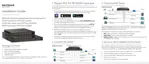
PoE Max LED in the Device View (Model GS324TP)
The PoE Max LED indicates the following status:
• Off. Sufficient (more than 7W of) PoE power is available.
• Solid yellow. Less than 7W of PoE power is available.
•
Blinking yellow.
At least once during the previous two minutes, less than 7W of PoE
power was available.
Interface Naming Conventions
The switch supports physical and logical interfaces. Interfaces are identified by their type and
the interface number. The physical ports are Gigabit interfaces and are numbered on the
front panel. You configure the logical interfaces by using the software.
The following table describes the naming convention for all interfaces available on the switch.
Table 3. Naming conventions for interfaces
Interface Description Example
Physical The physical ports are Gigabit Ethernet interfaces and are
numbered sequentially starting from 1.
g1, g2, g12
Link aggregation group (LAG) LAG interfaces are logical interfaces that are used only for
bridging functions.
l1, l2, l3
CPU management interface This is the internal switch interface that is associated with the
switch base MAC address.
The interface is not configurable
and is always listed in the MAC Address
Table.
c1
Configure Interface Settings
For some features that allow you to configure interface settings, you can apply the same
settings simultaneously to any of the following:
• A single port
• Multiple ports
• All ports
• A single LAG
• Multiple LAGs
• All LAGs
• Multiple ports and LAGs
• All ports and LAGs
 Loading...