S350 Series 24-Port (PoE+) and 48-Port Gigabit Ethernet Smart Managed Pro Switches
Monitor the System User Manual311
console log. Messages logged to a collector or relay through syslog support the same
format as well.
The following example shows the standard format for a log message:
<14> Mar 24 05:34:05 10.131.12.183-1 UNKN[2176789276]:
main_login.c(179) 3855 %% HTTP Session 19 initiated for user admin
connected from 10.27.64.122
The number contained in the angle brackets represents the message priority, which is
derived from the following values:
Priority = (facility value × 8) + severity level.
The facility value is usually 1, which means it is a user-level message. Therefore, to
determine the severity level of the message, subtract 8 from the number in the angle
brackets. The sample log message shows a severity level of 6 (informational). For more
information about the severity of a log message, see
Manage the Server Log on
page 313.
The message was generated on March 24 at 5:34:05 a.m. by the switch with an IP
address of 10.131.12.183. The component that generated the message is unknown, but it
came from line 179 of the
main_login.c file. This is the 3,855th message logged since
the switch was last booted. The message indicates that the administrator logged on to the
HTTP management interface from a host with an IP address of 10.27.64.122.
10. T
o refresh the page with the latest information about the switch, click the Refresh
button.
11. To clear the messages from the buffered log in the memory, click the Clear button.
Manage the Flash Log
The flash log is a persistent log, that is, is a log that is stored in persistent storage. Persistent
storage survives across platform reboots. The first log type is the system startup log. The
system startup log stores the first 32 messages received after system reboot. The second log
type is the system operation log. The system operation log stores messages received during
system operation.
To configure the flash log settings:
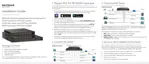
1. Connect your computer to the same network as the switch.
You can use a WiFi or wired connection to connect your computer to the network, or
connect directly to a switch that is of
f-network using an Ethernet cable.
2. Launch a web browser.
3. In the address field of your web browser, enter the IP address of the switch.
If you do not know the IP address of the switch, see
Discover or Change the Switch IP
Address on page 12.
The login window opens.
4. Enter the switch’s password in the Password
field.
 Loading...