Page | 84
SECTION 8.2 OUTPUT CONFIGURATION
FIGURE 8-17
Roll the mouse pointer over the Program monitor to reveal a Configure button (Figure 8-17) at right in the
titlebar below the display. Click it to open the Hardware Configuration panel.
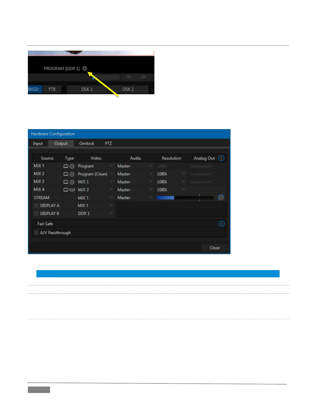
FIGURE 8-18
Note: The features shown in this panel vary by model.
8.2.1 OUTPUT TAB
The Output tab in the Hardware Configuration panel contains controls governing TriCaster’s outputs.
PRIMARY OUTPUTS
Depending on the model, either the first two (Mini SDI, Mini, and 2-RU models) or three (4-RU models) output
row entries correspond to physical output connectors. In addition, the first four entries are always exposed
to connected networks as NDI (Network Device Interface) outputs.
These primary outputs support the largest number of optional video sources and, uniquely, can follow a
delegated M/E or Switcher color group. All other outputs can be assigned to follow a primary output, or show
another designated Switcher source (excluding M/Es).
 Loading...