© 2011 Omnicell, Inc. 1-, 2-, 3-Cell Color Touch Installation and Service Guide/67-2014 Rev G
Frames and Wireways 2-11
Wireway Removal
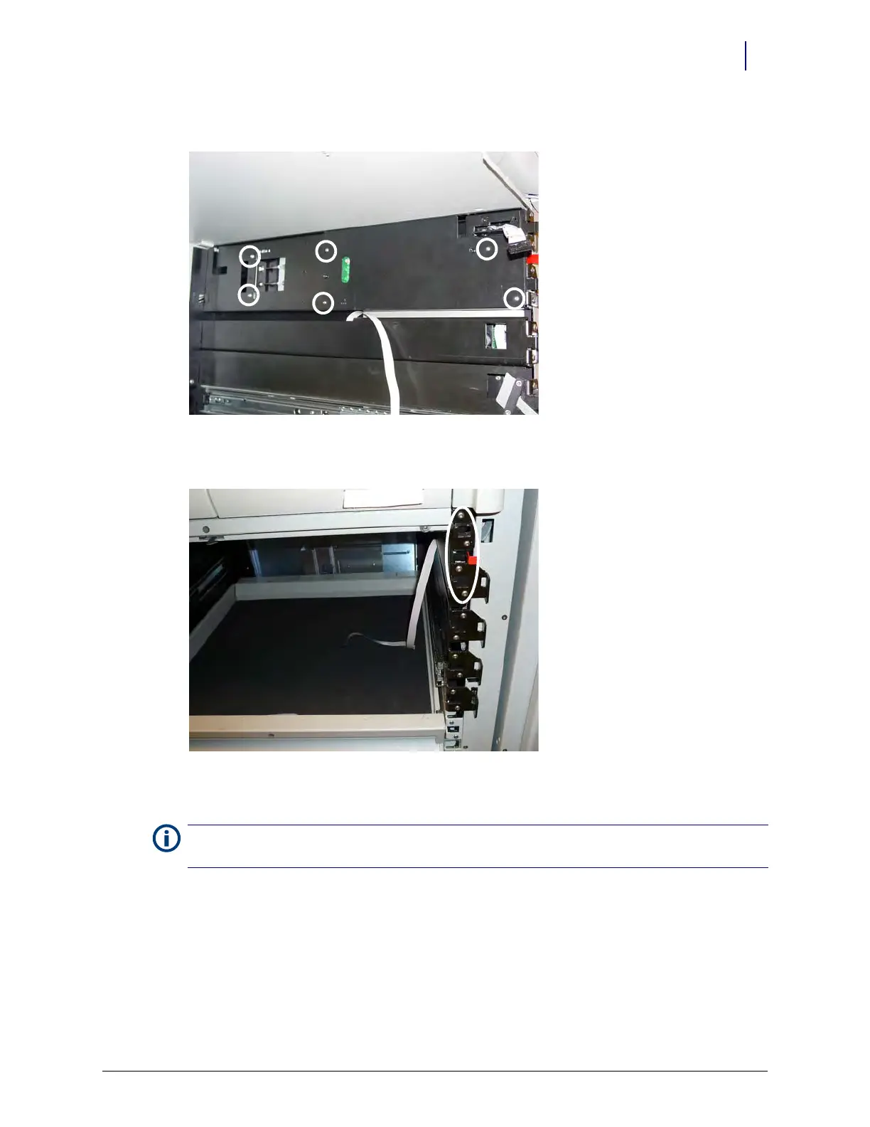
4. Remove the six screws securing the plate to the top bayonet on the right side of the frame.
Figure 2-18. Remove the screws securing the plate to the top bayonet
5. Remove the four screws that secure the top bayonet.
Figure 2-19. Remove the four screws that secure the top bayonet
6. Move the top bayonet slightly and disconnect the ribbon cable from the wireway.
7. Place one screw back in the top bayonet to secure the bayonet to the frame.
Note:
Do not attempt to remove the top bayonet from the frame. The manual override cables are attached to
the bayonet and removing the top bayonet will disable the functionality of the manual override.