6-12
6-4 Setting the Mode
Operation
6
I/O Signal Status
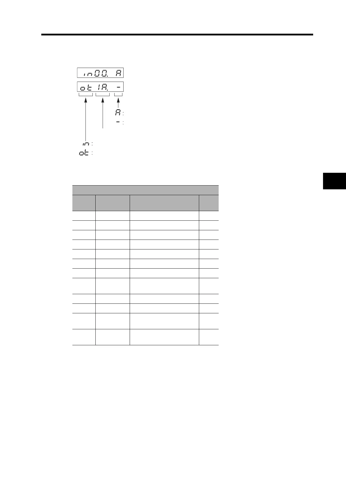
Displays the status of the control input and output signals connected to CN1.
Input Signals
CN1
Signal
No.
Abbreviation Name
Pin
No.
00 POT Forward Drive Prohibit Input 19
01 NOT Reverse Drive Prohibit Input 20
02 DEC Origin Proximity Input 21
06 EXT1 External Latch Signal 1 5
07 EXT2 External Latch Signal 2 4
08 EXT3 External Latch Signal 3 3
0A STOP Emergency Stop input 2
0B IN2
External General-purpose
Input 2
23
0C PCL Forward Torque Limit Input 7
0D NCL Reverse Torque Limit Input 8
0E IN0
External General-purpose
Input 0
22
0F IN1
External General-purpose
Input 1
6
Input signal No. 00 ON
Output signal No. 1A OFF or disabled
ON
OFF or disabled
Signal No. display (0 to 1F hex)
Input
Output

 Loading...


