6-13
6-4 Setting the Mode
Operation
6
Output Signals
Switching between Input and Output Signals
The following procedure can also be used to switch between inputs and outputs.
CN1
Signal
No.
Abbreviation Name
Pin
No.
00 READY Servo Ready ---
01 /ALM Alarm Output 15
02 INP1 Positioning Completed 1 Output ---
03 BKIR Brake Interlock ---
04 ZSPD Zero Speed Detection ---
05 TLIM Torque Limiting ---
06 VCMP Speed Conformity ---
09 TGON
Servomotor Rotation Speed
Detection
---
0F INP2 Positioning Completed 2 Output ---
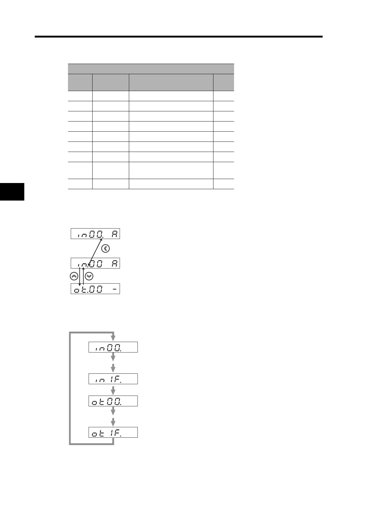
If the decimal point is at the right of the signal number,
the signal number can be changed.
If the decimal point is at the right of the input/output
indication, you can switch between inputs and outputs.
Move the flashing decimal point with the Shift key.
Switches between inputs and outputs.
Press the Increment or Decrement key to select the signal number to be monitored.
(Highest input signal number)
(Lowest input signal number)
(Lowest output signal number)
(Highest output signal number)

 Loading...


