8-11
8-3 Troubleshooting
Troubleshooting
8
29
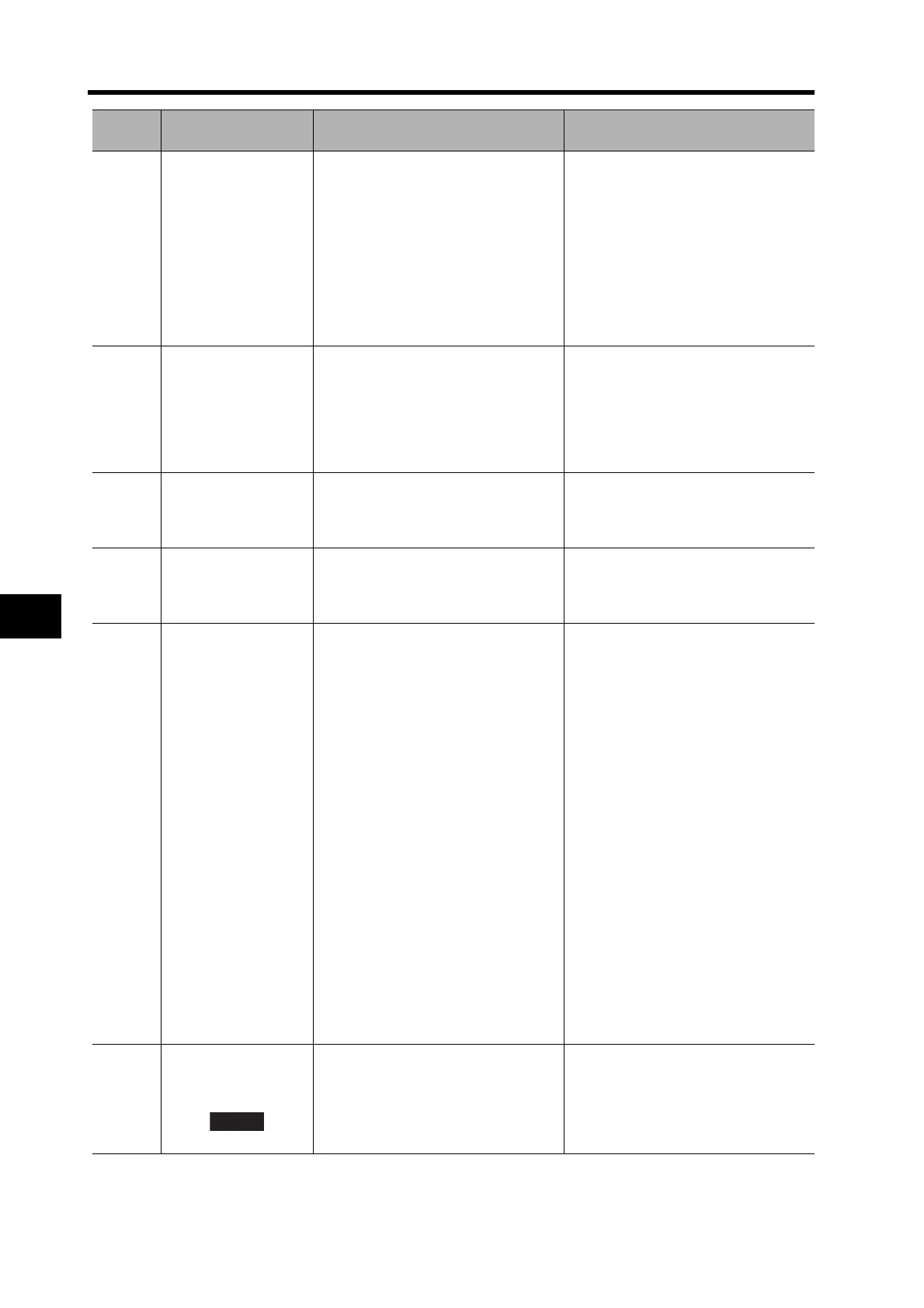
Internal deviation
counter overflow
The value of the internal deviation
counter (internal control unit) exceeded
2
27
(134217728).
Check that the speed monitor and
torque monitor values are indicated as
commanded by the Servo Drive. Check
that torque is not saturated. Check that
the No. 1 Torque Limit (Pn05E) and the
No. 2 Torque Limit (Pn05F) are not too
small.
Check by readjusting the gain,
increasing the acceleration / decelera-
tion times, and lowering the speed with
the reduced load.
34 Overrun limit error
The Servomotor exceeded the
allowable operating range set by the
Overrun Limit Setting (Pn026) with
respect to the position command input.
1 The gain is not appropriate for the
load.
2 The setting for Pn026 is too small.
1 Check the position loop gain,
speed loop gain, integration time
constant, and inertia ratio.
2 Increase the setting for Pn026.
Set Pn026 to 0 to disable the
protective function.
36 Parameter error
Data in the parameter save area was
corrupted when the data was read from
the EEPROM at power-ON.
If the warning continues to occur even
after retransferring all parameters, the
Servo Drive may have failed.
Replace the Servo Drive.
37 Parameter corruption
The EEPROM write verification data
was corrupted when the data was read
from the EEPROM at power-ON.
If the warning continues to occur even
after retransferring all parameters, the
Servo Drive may have failed.
Replace the Servo Drive.
38
Drive prohibit input
error
1 The Drive Prohibit Input Selection
(Pn004) is set to 0, and both
Forward and Reverse Drive
Prohibit Inputs (POT and NOT)
became OPEN.
2 The Drive Prohibit Input Selection
(Pn004) is set to 2, and either
Forward or Reverse Drive Prohibit
Input (POT or NOT) became
OPEN.
3 With the Drive Prohibit Input
Selection (Pn004) set to 0,
MECHATROLINK-II
communications interrupted, and
either Forward or Reverse Drive
Prohibit Input (POT or NOT) turned
ON, an operation command (jog
operation or normal mode
autotuning) was received via
RS232. Or, either POT or NOT
turned ON while operating on an
operation command received via
RS232.
Check the sensors, power supply, and
wiring for the Forward and Reverse
Drive Prohibit Inputs.
Also check that the response of the
power supply (12 to 24 VDC) is not too
slow.
Check that there is no command input
in the direction of the Drive Prohibit In-
put.
40
Absolute encoder
system down error
The power supply and battery voltage
to the encoder dropped below the
specified value. (3.0 V or less)
Connect the power supply for the
battery, and clear the absolute encod-
er. Refer to Absolute Encoder Setup on
page 6-6.
Initial setup of the absolute encoder
must be performed to clear the alarm.
Alarm
code
Alarm Name Cause Countermeasure

 Loading...


