2-38
2-2 External and Mounting Hole Dimensions
2
Standard Models and Dimensions
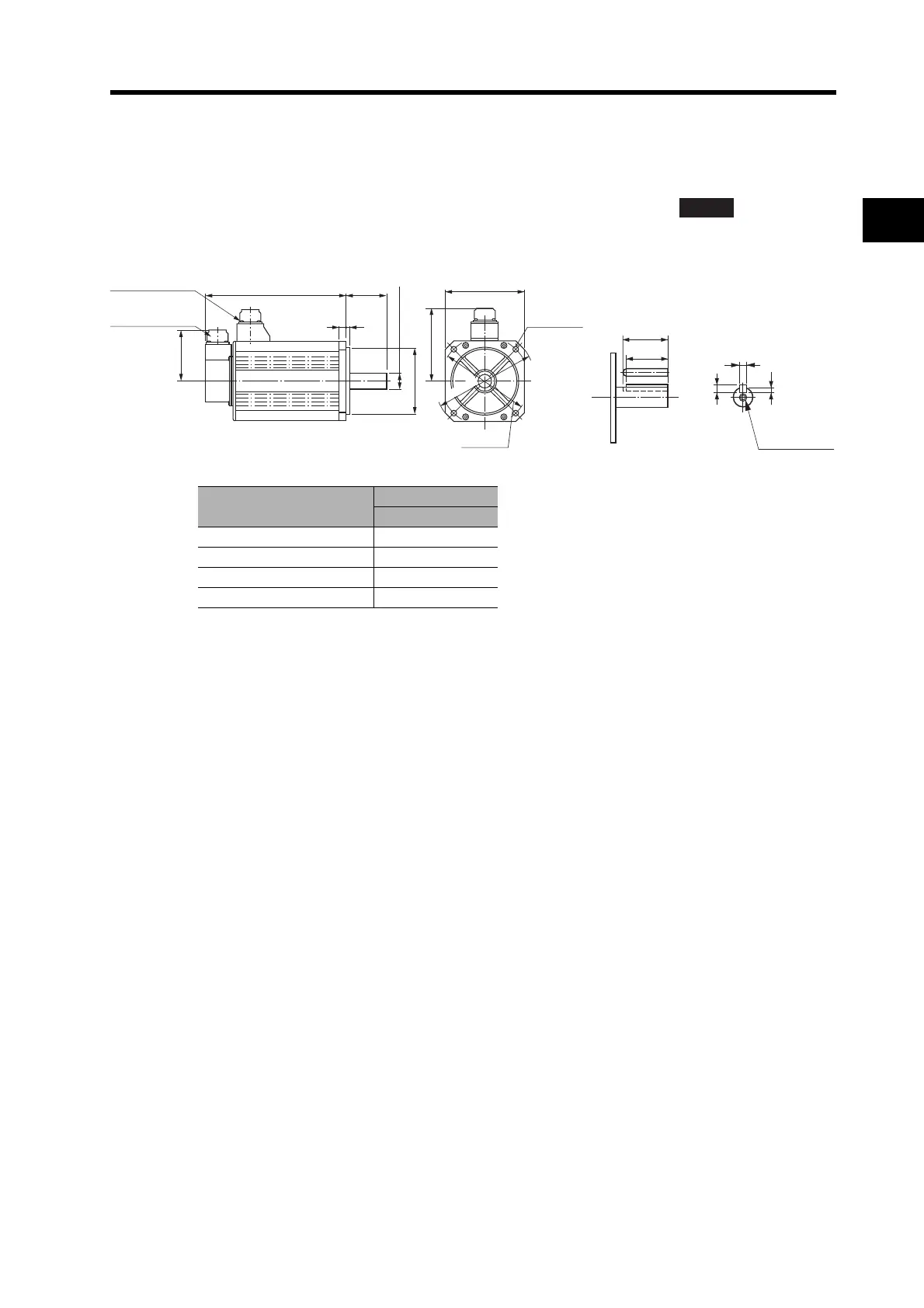
3,000-r/min Servomotors
4 kW/5 kW
R88M-G4K030T(-S2)/-G5K030T(-S2)/-G4K030T-B(S2)/-G5K030T-B(S2)
Note The standard models have a straight shaft. Models with a key and tap are indicated with
"S2" at the end of the model number.
Model
Dimensions (mm)
LL
R88M-G4K030 240
R88M-G5K030 280
R88M-G4K030-B 265
R88M-G5K030-B 305
ABS
LL
65
12
6
118
84
130×130
Four, 9 dia.
110 dia., h: 7
24 dia., h: 6
165 dia.
Encoder
connector
Servomotor/brake
connector
145 dia.
55
51
Eight, h: 9
4
7
M8 (depth: 20)
(Dimensions of shaft end
with key and tap)
 Loading...


